
Background
In order to provide a better understanding, a list of terms using in this project is presented below.
DVB-S
The Digital Video Broadcasting – Satellite (DVBS) was released in 1995. The purpose was to normalize the physical link characteristics and frame structure for satellite. With the fast development of the digital satellite transmission technologies, it comes to the second version in 2005, Digital Video Broadcasting - Satellite - Second Generation systems (DVB-S2). The second generation achieves a better performance allowing for an increase of available bit rate over the same bandwidth. The data format in DVBS supports the MPEG transport stream while DVB-S2 uses the Generic Stream Encapsulation. Comparing with the fact that DVBS only specifies physical link, DVB-S2 is improved owing to the implementation of low density parity check codes (LDPC), which require less power efficiency. Thus, the results of DVB-S2 are more flexible with lower cost for the customers.
The main characteristics are shown in the following table:
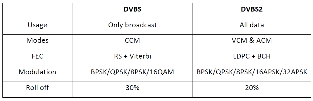
Table 1. DVBS vs DVBS2
QPSK
Quadrature phase-shift keying (QPSK) is a digital modulation scheme. As shown in the figure below, it uses four phases which are separated by 90° so it is also termed 4PSK. With these four phases, it is available for QPSK to encode two bits per symbols, that is why a QPSK symbol represents 00, 01, 10, 11. It conveys data by changing the phase of a receiving signal. Nowadays, it is widely used in the wireless communications such as DVBS satellite system, owing to its strong ability of anti-interference and bandwidth efficiency.
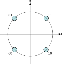
Figure 1. QPSK constellation
A brief introduction of QPSK transmitter and receiver is useful for the Labview implementation later.
In QPSK transmitter, as shown in the figure 2, the binary data stream is divided into two parts, the in-phase and quadrature-phase components. Then we get two corresponding digital signals. After the polar non-return-to-zero(NRZ) encoding, two relevant analog signals are generated. Afterwards, the signals are separately modulated into two orthogonal basis functions. Finally, we get the QPSK signal.
![]()
Figure 2. QPSK transmitter
Figure 3 is the structure of QPSK receiver. We use the matched filter to get the in-phase and quadrature-phase components of signals. After two-dimensional matched filters, the signals are followed by a sampler to reduce the noise, and then generate the binary data stream by a decision device.
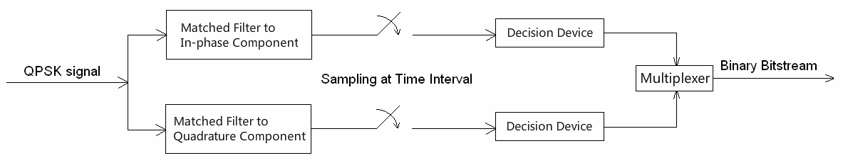
Figure 3. QPSK receiver
GEO
The geostationary satellite (GEO) is widely used nowadays. There are around 200 geostationary satellites within the 360° orbital architecture in operations. They have circular orbits with zero inclination and their orbits around the earth are at an altitude of 35786km according to the earth rotation. Moreover, the period is equal to 23hours 56 minutes and 4 seconds. Only three distributed geostationary satellites separated by 120° can cover the global earth. Thus the satellite ensures continuous operations as a radio relay in real time for the area of visibility.
However, it is unavoidable to have the delay from the transmission between the satellite and the ground. In order to solve this problem, geostationary satellite has been developed to the ninth generation. Nowadays, the best example is Intelsat I-IX satellite of the International Satellite Communications.