I - Equipment
A CubeSat is a miniaturized satellite for space research. Multiple cubic units compose its structure and each unit has a size of 10*10*11.35 cm for a mass of no more 1.33 kg per unit. These specifications and standards were developed by Jordi Puig-Suari from California Polytechnic State University in 1999 [1]. Thus, the size of CubeSat, composed of one, two or three units for the majority, and its weight allow universities and educational institutions to have an access to space exploration and research for a low cost (less than $150 000, launch and manufacturing cost all-inclusive).
In 2003, the first CubeSat was launched. By 2015, more than 250 CubeSats have been put in the orbit. Academia accounted for the majority of CubeSat launches until 2013 when over half of launches were for non-academic purposes, and by 2014 most newly deployed CubeSats were for a commercial or amateur project. CubeSats have been built by large and small companies alike, while other projects have been the subject of Kickstarter campaigns. In order to reduce more and more the cost of launches, Cubesats are generally sent with other bigger missions.
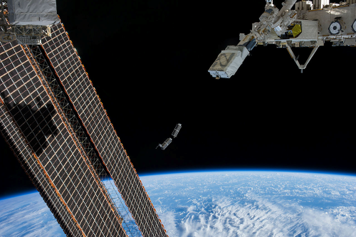
NanoRacks CubeSats being launched from the NanoRacks CubeSat Deployer on the ISS on February 25, 2014.
[1] Arash Mehrparvar, CubeSat Design Specification rev 13, 2014
web page : http://www.cubesat.org/images/developers/cds_rev13_final.pdf
[2] Woellert et al., Cubesats: Cost-effective science and technology platforms for emerging and developing nations, 2011
web page : https://www.gwu.edu/~spi/assets/docs/Woellert_cubesats.pdf
[3] "Tiny Cubesats Set to Explore Deep Space". Space.com, 2015
Web page : http://www.space.com/29306-cubesats-deep-space-exploration.html
For overall information : wikipedia
Web page : https://en.wikipedia.org/wiki/CubeSat
Devise used in our project: the dsPIC33FJ256GP710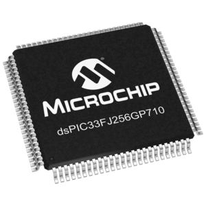
This electronic component is a 16-bit processor where we will implement our error correction encoder and decoder. Its characteristics are:
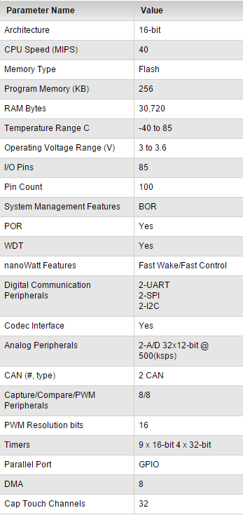
Note: MIPS = million instructions per second in the Central Processing Unit.
Website of this device's specifications: http://www.microchip.com/wwwproducts/Devices.aspx?product=dsPIC33FJ256GP710
The development board and components used for the tests on error correcting codes.
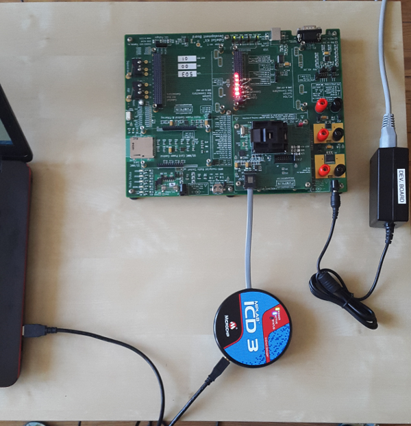
In order to check if the program is working well or not, an input information word is need inside the processor for the simulation of error correcting code. This message will be encoded and decoded according to the program called in the device. But it is also necessary to observe the different steps of the process, therefore we had to imagine a solution which allows us to see the message at each step. Thus, six LEDs protected by six resistances (some hundreds of Ohms) were added to the development board that allow us to keep an eye on six bits of the message.
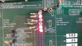
View of LEDs and Resistances on board
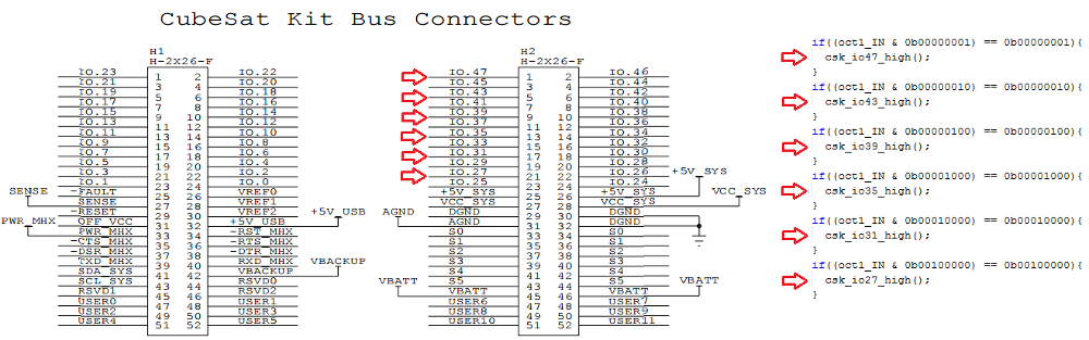
Bus connector and extract from the code that lights up LEDs
