
Application » History » Version 49
« Previous -
Version 49/50
(diff) -
Next » -
Current version
HAENNIG, Gerald, 12/16/2015 02:07 PM
- Table of contents
- 4. Results
4. Results
This section explains how the Outdoor system has been installed and the results obtained measuring a real TV signal from a Satellite.

Optical system (transmitter + fiber + receiver)
4.1 Preparation
The optical transmitter has been put in an hermetic box.

Hermetic box installed outdoors
Its interface consists of :
- The power supply plug to be connected to the mains ;
- The optical fiber harness (2 fibers) : only the red fiber is actually connected to optical transmitter ; the black fiber is not used, it will enable to have a b.
- The type F coaxial cable to connect the Antenna Low Noise Block, LNB, to optical transmitter.
Optical transmitter is set to :
- To supply 18 V to LNB, which selects Horizontal polarization.
- To provide 0 kHz tone to LNB, which set its Local Oscillator to 9.75 GHz to transpose lower Ku Band from 10.7 to 11.7 GHz into IF Band.
- This hermetic box has been mounted on Antenna mast. This Antenna is pointing to Astra 1KR/1L/1M/1N co-localized satellites on 19.2° East.
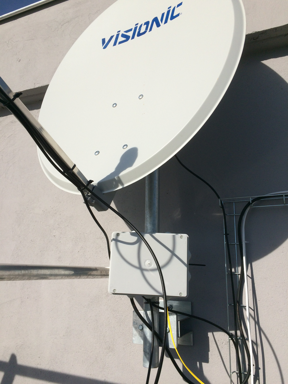
Hermetic box installed on Antenna Mast
4.2 Trials
4.2.1 Inter Frequency Spectrum with Optical Link
RF output from Optical receiver has been analyzed with Rohde & Schwartz FSV spectrum analyzer :

IF Band, 1 Channel (with Optical Link)
It is possible to distinguish several channels within the Inter Frequency, IF, band. There is a zoom on left side. The 3 dB channel bandwdith is 22 MHz.
The power is about -32 dBm for the channel centered around 1141 MHz.

TV channel at 1141 MHz
4.2.2 Link Quality with Optical link

Measurement setup based on TV, Tuner, IPRICOT SCB router with Optical Receiver (On screen : Einsfestival program on 10744 MHz Horizontal Polarization)
First, optical link performance enables to have a good TV quality (for example, Einsfestival Plus on 10744H).
Channel power and 3 dB Channel bandwidth have been checked with Spectrum Analyzer.
More deeply, physical link quality has been assessed with the information provided by IPRICOT SCB router :- IPRICOT confirms that input signal is a QPSK modulation with Forward Error Correction Rate of 5/6 (RX_SIG & VITSYNC set to green). Moreover, IPRICOT is able to get the Frame Synchronization (FSYNC set to green) ;
- Eb/No is reported by IPRICOT.
This data has been compared with data from website like [www.lingsat.com] :
| Ku Channel [MHz] | IF Channel [MHz] | TV | www.lingsat.com | Spectrum Analyzer | IPRICOT | |||
|---|---|---|---|---|---|---|---|---|
| Channel | Physical Protocol | EIRP[dBW] | 3dB CH BW [MHz] | CH Power [dBm] | Physical Protocol | Eb/No[dB] | ||
| 10744H | 994 | Eins Plus | DVB-S QPSK 22 Msps 5/6 | About 22 | -31.44 | DVB-S QPSK 22 Msps 5/6 | 7.7 | |
| 11244H | 1494 | Schau TV | DVB-S QPSK 22 Msps 5/6 | About 22 | -32.31 | DVB-S QPSK 22 Msps 5/6 | 7.9 | |

Physical link parameter at 10744 MHz
4.2.3 Link Quality with Coaxial Cable
Optical link have been replaced by coaxial cable. Similar measurements have been carried out.
A splitter is used to measure the spectrum : this loss has to be taken into account.
Antenna coaxial cable was directly connected to IPRICOT SCB router.
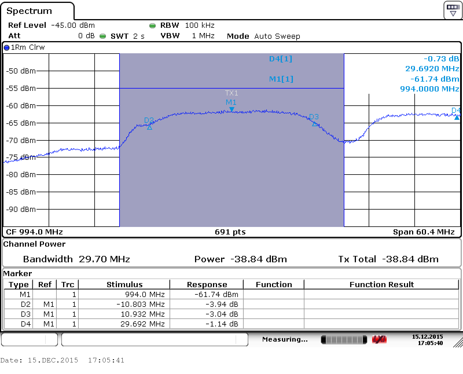
Spectrum at 944 MHz (related to 10744 MHz H)

Physical link parameter at 10744 MHz
4.2. Result analysis : comparison coaxial cable vs optical link
| Ku Channel [MHz] | IF Channel [MHz] | Optical link | Coaxial Cable | ||
| CH Power [dBm] | Eb/No[dB] | CH Power [dBm] | Eb/No[dB] | ||
| 10744H | 994 | -31.44 | 7.7 | -32.84 | 7.4 |
| 11244H | 1494 | -32.31 | 7.9 | -36.67 | 8.0 |
Performances sounds to be quite similar.