
- Table of contents
- 3.1 Continuous Wave Radio-Frequency Gain for opitcal link (transmitter+fiber+receiver)
3.1 Continuous Wave Radio-Frequency Gain for opitcal link (transmitter+fiber+receiver)
A Continuous Wave Radio-Frequency,CW RF, signal is generated with the Keysight N9310A Signal Generator. This signal is provided to the optical transmitter which converts it into an optical signal which intensity is modulated by RF carrier. The optical recevier converts the optical signal back to an CW RF signal. This signal is measured on the FSV spectrum Analyzer.
The gain is measured as : Gain = RF POWER [dBm] Optical Receiver Out - RF POWER [dBm] Optical Transmitter In.
3.1.1 Gain Linearity
Optical link overall response is linear within its operating input power dynamic : optical transmitter and receiver are both linear according to the specifications described on Elements and technical features between 0.7 and 2.1 GHz. Low signal distortion is expected.
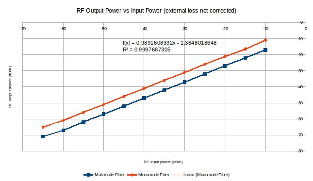
Figure 1. RF Gain Linearity of Optical Link.
For Figure 1 it has also been compared the gain for a monomode and a multimode fiber, concluding that the monomode fiber has a higher gain than the multimode.
3.1.2 Frequency Response
Optical link frequency response has a shape of a low path filter : the 3 dB cutoff frequency is above 2300 MHz. Thus, the optical link is meeting its specification and is able to support the total Inter Frequency, IF, band.
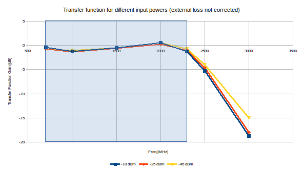
Figure 2. RF frequency respone (for several RF input powers).
3.1.3 RF Gain
As they are lossy coaxial cables to connect signal generator to the optical transceiver and optical receiver to spectrum analyzer, this losses have be to taken into account.
Optical link RF Gain has been measured with these corrections and the results are contained in the following figure.

Figure 3. RF Gain (cable loss removed).
As it can be observed in Figure 3 within the frequency interval specification the gain is always positive arriving until its maximum (around 3.5dB) at 2GHz.