
1. Network architecture
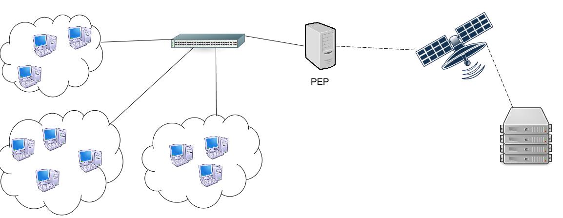
Figure 1 : Architecture of a classical telecommunication network using PEP
This figure shows a classical network using PEP. It is asymmetric because on one side of the satellite link we have a server and on the other side we have all the terminals.
In this project we can not use a real satellite so we need to emulate this link. Consequently the network architecture we want to implement is quite different and is shown on the next figure.
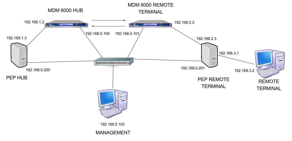
Figure 2 : Architecture we want to implement on the lab
With this architecture, we juste need to add a delay to the packets between the two PEPs to simulate the satellite link.
The network 192.168.0.0/24 is used for the management of the PEPs and the modems.