Technical Generalities and requirements » History » Version 11
« Previous -
Version 11/18
(diff) -
Next » -
Current version
BASTIDE, Paul, 03/23/2016 02:45 PM
- Table of contents
- Principle of a thermocouple
- RF transmission channel
- RTOS
Principle of a thermocouple
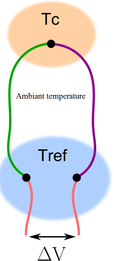
To measure the temperature, we are going to use a thermocouple. It consists of two conductor wires which are welded at one end and free at the other. The welded part is to be placed where the temperature has to be measured. By measuring the potential difference between the two ends of the wire and knowing the type of material that was used, we can obtain the wanted temperature.

Figure 1 : Principle of a thermocouple
The physical phenomenon that is used is the Seedbeck effect. It implies that, when there is a gradient of temperature in a conductive material, an electromotrice force is observed. Therefore, if we place this conductive material in an open circuit without internal current flow , the gradient of temperature is proportionnal to the gradient of voltage.
grad(V)= -S(T)* grad(T)
S(T) is the seedbeck coefficient and it depends on the material that was used and the temperature. Of course, the reference temperature has to be known in order to get the actual temperature.
Different types of thermocouple exist using different conductive materials. They provide different range of temperature and are more or less precise. Their resistance to radiation is as well different and so is their stability. (the full list is available at...)
For each type of thermocouple, there are tables linking the difference of potential at the extremities of the wire to the temperature in degrees celsius.
RF transmission channel
In order to fulfill our mission, we need to set into place a simple RF communication channel. Indeed, the temperature that will be measured and sent will be a real number which will be coded in a certain number of bits. Depending on the number of bits, the range of the possible temperature will vary. Those bits will be transmitted to the transceiver and sent to the receiver. The transceiver, in the emitter case, is in charge of transforming the bits (0 and 1) into symbols, modulating them and generating the RF signals to be transmitted in pass band. For the receiver case, it is in charge of receiving the RF signals, demodulating them and finally translating into bits again.
That leads to a communication system as follow:

Figure 2 : RF communication chain
RTOS
Cubesat is working on a DSPIC33F processor, which is a small Microcontroller Unit (MCU), working on a 16-bits basis. Digital Signal Controller is a mix between a microcontroller and a digital signal processor.
As the Cubesat has a mission to accomplish, it needs a software to handle and distribute data, and most of the time in real time. Those kind of software are called Real Time operating System (RTOS). An RTOS is used to distribute processing power between different processes that should be running simultaneously. There is two main strategies ruling that distribution: time based sharing, and event-driven. Time based sharing synchronize the switching between tasks with a clock, while an event-driven RTOS introduces priorities between tasks: when a higher priority task needs to run, it interrupts low-level tasks to monopolize processing power.
The RTOS chosen on the Cubesat standard is Pumpkin’ Salvo RTOS, an RTOS build to work on small RAM DSCs. This RTOS is an event driven RTOS.

