3. SDR Signal Analyser – Digital Measurements
Reminder: Digital measurements will display:- Constellation of the received signal
- Magnitude error
- Phase error
- Error Vector Magnitude
The digital measurements are carried out on the “Digital” tab. Here, it is possible to configure the USRP and control all the parameters that need to be known to successfully display the constellation of the signal to be analysed. The below table sums up the parameters that have been entered as inputs according to the parameters of the signal to be analysed.

Figure 25: Characteristic of the signal to be analysed (Reference here)
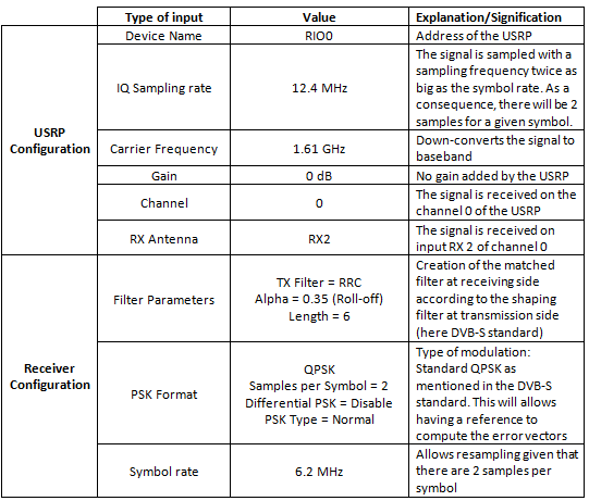
Table 5: Input parameters for digital measurements
The results of the digital measurements are displayed on the following figure.

Figure 26: Results of the Digital measurements of the SDR Signal Analyser
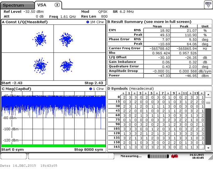
Figure 27: Results of the Digital measurements of the Rohde&Schwarz signal analyser

Table 6: Comparison of the digital measures
As the acquisition duration to display the constellation - and compute the error measurements associated - is larger on the SDR signal analyser than the Rohde&Schwarz one, fewer samples are displayed on the constellation of the Rohde&Schwarz signal analyser. As a result, the displayed samples are less likely to be spread around the ideal symbols. Thus, the error measurements derived from the constellation of the Rohde&Schwarz signal analyser are slightly lower the ones of the SDR signal analyser. Nonetheless, the digital measurements from the SDR signal analyser seem to match those from the Rohde&Schwarz signal analyser. Therefore, the digital measurements are valid.
