
PART » History » Version 32
« Previous -
Version 32/35
(diff) -
Next » -
Current version
COLIN, Tony, 03/14/2016 10:39 AM
PART 2 : GPS signals generation.
- Table of contents
- PART 2 : GPS signals generation.
In order to design a software-defined single frequency GPS receiver it is necessary to know the characteristics of the signal and data transmitted from the GPS satellites and received by our GPS receiver antenna. In this part an overview of the GPS signal generation scheme and most important properties of the various signals and data are presented.
1 - GPS signals.
The GPS signals are transmitted on two radio frequencies in the UHF band. The UHF band covers the frequency band from 500MHz to 3GHz. These frequencies are referred to as L1 and L2 and are derived from a common frequency f_0 = 10.23MHz :
f_L1 = 154 x f_0 = 1575.42MHz and f_L2 = 120 x f_0 = 1227.60MHz.
The signals are composed of the following three parts :
- Carrier : The carrier wave with frequency f_L1 or f_L2
- Navigation Data (D) : The navigation data contain information regarding satellite orbits. This information is uploaded to all satellites from the ground stations in the GPS Control Segment (Cf. Part1 - 5). The navigation data have a bit rate of 50bps.
- Spreading sequence (C) : Each satellite has two unique spreading sequences or codes. The first one is the coarse acquisition code (C/A), and the other one is the encrypted precision code (P(Y)). The C/A code is a sequence of 1023 chips, with a chip corresponding to a bit. The code is repeated each ms giving a chipping rate of 1.023 MHz. The P code is a longer code with a chipping rate of 10.23 MHz and will not be taken into account in this project.
The C/A code in only modulated onto L1 carrier while the P(Y) code is modulated on both L1 and L2 carrier.
The figure shows the three parts forming the signal on the L1 frequency. The C/A code repeats itself every ms, and one navigation bit lasts 20ms. Hence for each navigation bit, the signal contains 20 complete C/A codes.

Figure 2.1 : Signal decomposition.
The figure shows the Gold code C, the navigation data D, the modulo-2 added signal C⊕D and the carrier. The final signal is created by binary phase-shift keying (BPSK) where the carrier is instantaneously phase shifted by 180° at the time of a chip range. When a navigation data bit transition occurs (about one third from the right edge), the phase of the resulting signal is also phase-shifted 180°.
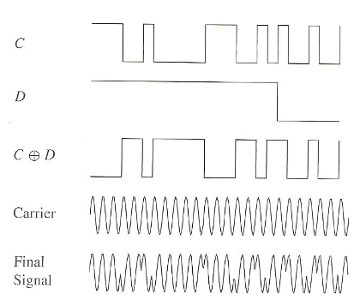
Figure 2.2 : Operation on the data
2 - Navigation Data.
The navigation data are transmitted on the L1 frequency with the earlier mentioned bit rate of 50 bps. This section describes the structure and contents of the navigation data. The figure shows the overall structure of an entire navigation message.
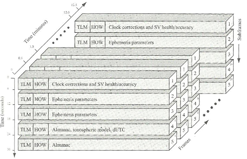
Figure 2.3 : Frame decomposition through time from [1].
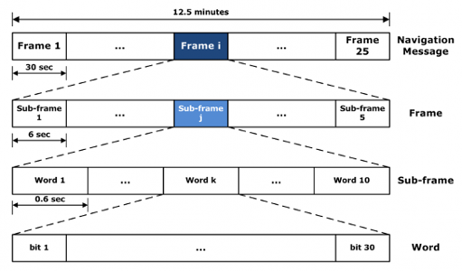
Figure 2.4 : Frame decomposition seen as encapsulation from [2].
The basic format of the navigation data is 1500-bit-long containing 5 subframes, each having length 300 bits. One subframe contains 10 words, each word having length 30 bits. Subframe 1,2 and 3 are repeated in each frame. The last subframes, 4 and 5, have 25 versions (with the same structure, but different data) referred to as index 1 to 25. With the bit rate of 50 bps, the transmission of a subframe lasts 6 s, one frame lasts 30 s, and one entire navigation message lasts 12.5 minutes.
a- Telemetry and Handover Words.
The subframes of 10 words always begin with two special words, the telemetry (TLM) and handover word (HOW) pair.
TLM is the first word of each subframe and it is thus repeated 6 s. It contains an 8-bit preamble followed by 16 reserved bits and parity. The preamble should be used for frame synchronization.
HOW contains 17-bit truncated version of the Time Of the Week (TOW), followed by two flags supplying information to the user of antispoofing etc. The next 3 bits the subframe ID to show in which of the five subframes in the current frame this HOW is located.
b- Data in Navigation Message.
In addition to the TLM and HOW words, each subframe contains 8 words of data. This will only be a cursory description of the data in the different words and not a complete description of all bits.
Subframe 1 - Satellite Clock and Health Data : The first subframe contains first of all clock information. That is information needed to compute at what time the navigation message is transmitted from the satellite. Additionally, subframe 1 contains health data indicating whether or not the data should be trusted.
Subframe 2 and 3 - Ephemeris Data : The ephemeris data relate to the satellite orbit and are needed to compute satellite position.
Subframe 4 and 5 - Support Data : As mentioned, the last two subframes repeat every 12.5 minutes, giving a total of 50 subframes. Subframes 4 and 5 contain almanac data. The almanac data are the ephemerides and clock data with reduced precision. Additionally, each satellite transmits almanac data for all GPS satellites while it only transmits ephemeris data for itself. The remainder of subframes 4 and 5 contain various data e.g. UTC parameters, health indicators, and ionospheric parameters.
More details available under GPS specifications [3] - Part : Navigation Data Message Stucture.
3 - C/A code : Spread Spectrum & Gold Sequence.
In this section, the spreading sequences used in GPS are described. We restrict ourselves to the C/A code sequences, as we deal only with L1 signals in this project. The spreading sequences used C/A codes in GPS belong to a unique family of sequences. They are often referred to as Gold codes or also as pseudo-random noise (PRN) sequences, because of their characteristics.
a- Gold Sequence.
The PRN codes transmitted by the GPS satellites are deterministic sequences with noiselike properties. Each C/A code is generated using a tapped linear feedback shift register (LFSR). It generates a maximal-length sequences of N=2^n-1 elements.
The Gold code is the sum of 2 maximum-length sequences. The GPS C/A code uses n=10. The sequence p(t) repeats every ms so the chip length is 1ms/1023=977.5 ns≈*1µs*, which corresponds to a metric length of 300m when propagating through vacuum of air.
The autocorrelation function for this C/A code is

Figure 2.5 : C/A code autocorrelation (R1).
The sequence would 512 ones and 511 zeros, and these would appear to be distributed at random. Yet the string of chips so generated is entirely deterministic. The sequence is pseudorandom, not random. Outside the correlation interval the autocorrelation function of p(t) is -1/N=-1/1023 for the C/A code.
The autocorrelation function can be expressed as the sum of this constant term and an infinite series of the triangle function r_x (τ). This infinite series is obtained by the convolution of r_x (τ) with an infinite series of impulse functions that are phase-shifted by mNT_c :
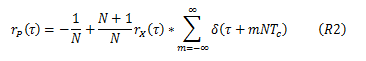
Figure 2.6 : C/A code autocorrelation (R2).
The power spectrum of this PRN sequence is derived from Fourier transform of (R2) :

Figure 2.7 : PRN sequence power spectral density (S).
b- Gold Sequence Generation.
The generation of the Gold codes is sketched in the following figure.
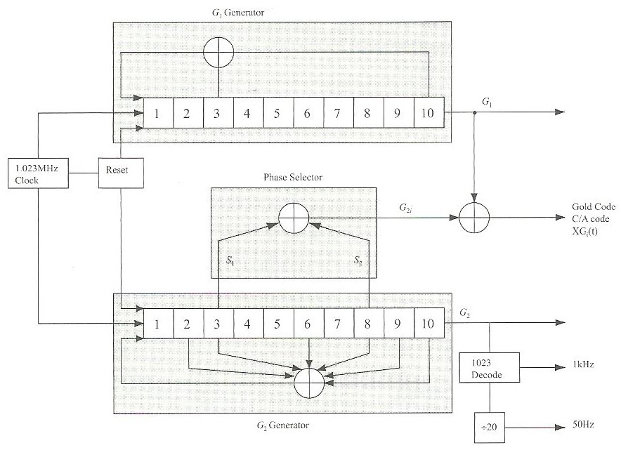
Figure 2.8 : Gold Sequence generation.
The C/A code generator contains 2 shift registers known as G1 and G2. These shift registers each have 10 cells generating sequences of length 1023. The 2 resulting 1023 chip-long sequences are modulo-2 added to generate a 1023 chip-long C/A code, only if the polynomial is able to generate code of maximum length.
Every 1023rd period, the shift registers are reset with all ones, making the code start over. The G1 register always has a feedback configuration with the polynomial :
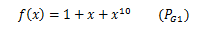
Figure 2.9 : Polynomial generator 1.
meaning that state 3 and state 10 are fed back to the input. In the same way, the G2 register has the polynomial :
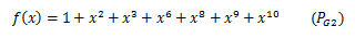
Figure 2.10 : Polynomial generator 2.
To make different C/A codes for the satellites, the output of the 2 shift registers are combined in a very special manner. The G1 register always supplies its output, but G2 register supplies 2 of its states to a modulo-2 adder to generate its output. The selection of states for the modulo-2 adder is called the phase selection. The next table shows the combination of the phase selections for each C/A code. It also shows the first 10 chips of each code in octal representation.
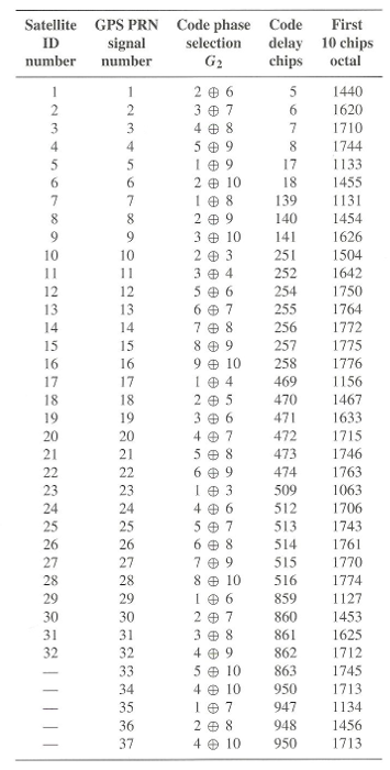
Figure 2.11 : Code phase selection per satellite ID.
c- Correlation Properties.
The Gold codes are selected as spreading sequences for the GPS signals because of their characteristics. The most important characteristics of the C/A codes are their correlation properties.
The 2 important correlation properties of the C/A codes can be stated as follows :
.........
4 - Signal Scheme overview.

Figure 2.12 : Emitter scheme of GPS signal.
The block diagram should be read from left to right. At the far left, the main clock signal is supplied to remaining blocks. The clock signal has a frequency of f_0=10.23MHz. When multiplied by 154 and 120, it generates the L1 and L2 carrier signals, respectively. At the bottom left corner a limiter is used to stabilize the clock signal before supllying it to P(Y) and C/A code generators. At the very bottom the data generator generates the navigation data D. The code generators and the data generator are synchronized through the X1 signal supplied by the P(Y) code generator.
After code generation, the codes are combined with navigation data through modulo-2 adders. The C/A ⊕ data and P(Y) code ⊕ data signals are supplied to the two modulators for the L1 frequency. Here the signals are modulated onto the carrier signal using BPSK method. Note that the two codes are modulated in-phase and quadrature with each other on L1. That is, there is 90° phase shift between the two codes. After the P(Y) part is attenuated 3dB, these two L1 signals are added to form resulting L1 signal. In our project, the so-called Standard Positioning Service (SPS) is based on C/A code signals alone.
It follows that the signal transmitted from satellite k can be described as :
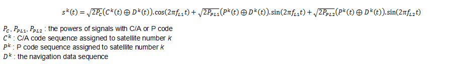
Figure 2.13 : GPS signal with relevant parameters.
References :
[1] K. Borre, D. M. Akos, N. Bertelsen, P. Rinder, S. H. Jensen, A software-defined GPS and GALILEO receiver
[2] http://www.navipedia.net/index.php/GPS_Navigation_Message
[3] http://www.gps.gov/technical/ps/1995-SPS-signal-specification.pdf