
PART2 » History » Version 25
« Previous -
Version 25/44
(diff) -
Next » -
Current version
JANVIER, Thibault, 03/22/2016 04:35 PM
PART 3 : Acquisition and Tracking.
- Table of contents
- PART 3 : Acquisition and Tracking.
1- Introduction.
a- General overview of a GPS receiver using CDMA technique.
The GPS signal generation scheme has been detailed in PART 2 and is using a CDMA technique which spreading sequences are the PRN codes. Thereby, the major steps of the whole communication chain can be summarized by the figure below.
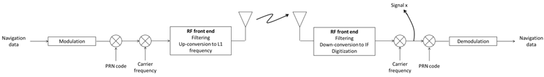
Figure 3.1 : GPS Communication Chain Overview.
Now that the transmitting side has been detailed in PART 2, it is possible to focus on the receiving side.
The receiving front-end filters, down converts to an intermediate frequency and digitizes the received signal. Thus, the signal still has to be down converted to baseband and to have its spreading sequence removed before being able to demodulate and recover the actual navigation data. The down-conversion to baseband is done by multiplying the signal at the output of the receiving front-end by a local carrier frequency which frequency matches the one of the received carrier. Therefore, the baseband signal x can be expressed as follows:

Figure 3.2 : Expression of the signal after downconversion to baseband .
Where:
A is the amplitude of the signal
τ_j = jT is the sampling time
T is the sampling period
td(τ_j) is the time difference between the start time of the navigation sequence and τ_j . In other words, τ_j - td(τ_j) represents the actual phase of the incoming navigation data at time τ_j.
ts(τ_j) is the time difference between the start time of the spreading sequence and τ_j. In other words, τ_j – ts(τ_j) represents the actual phase of the incoming PRN sequence.
θ is the phase shift due to non-coherent down-conversion to baseband (Doppler shift)
n is a white Gaussian noise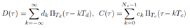
T_d is the symbol period
T_c is the chip period
d_k is a navigation symbol taking its values in ±1
c_k is a chip symbol taking its values in ±1
π_Td is the standard pulse function of width Td
π_Tc is the standard pulse function of width Tc
N_c is the number of chips in one spreading code
Then, by generating a local spreading sequence that is similar to the received one and which phase matches the received one, the spreading code is removed from the signal and it is possible to retrieve the useful data.
The principle seems simple to understand, however, it highlights some practical issues that are depicted in the next subsection.
b- List of the key parameters in the implementation of a GPS receiver.
To decode navigation data, one first needs to remove the incoming carrier from the signal. To do so, the carrier frequency has to be known to generate a local carrier signal and down-convert the incoming signal to baseband. Nonetheless, this carrier frequency might deviate from the expected value. Indeed, the relative motion of the satellite with respect to the receiver induces a Doppler effect that shifts the frequency of the incoming carrier. If the GPS receiver is moving, it is reasonable to assume that the maximum Doppler shift for the L1 frequency is around ± 10 kHz. Otherwise, for a stationary GPS receiver, the maximum Doppler shift for the L1 frequency is around ± 5 kHz. Once the carrier frequency is known, its phase has to be determined as well in order to have a coherent demodulation that limits the bit error rate. These uncertainties regarding the carrier frequency and its phase will have to be dealt with in the implementation of the GPS receiver.
Another key parameter is related to the PRN sequences that are used to spread the information. First of all, the satellites are differentiated by 32 different PRN sequences. Consequently, the GPS receiver has to search for the right PRN code among all the PRN sequences to remove it from the signal and decode the data. Still, knowing the right PRN code to despread the signal at the receiving side is not sufficient. Indeed, PRN codes have high correlation only for zero lag. As such, it is of prime concern to know the incoming code phase in order to generate a local PRN code that is perfectly aligned with the incoming one. In addition, the Doppler shift induces a jitter regarding the actual duration of a PRN code. Thus, the local PRN code will have to be generated taking into consideration the phase and the jitter. The software-defined GPS receiver will have to address and overcome these issues.
The practical issues that have just been highlighted can be overcome using two major processes known as acquisition and tracking (see Figure 3.4). These processes will be carefully depicted in the following sections.
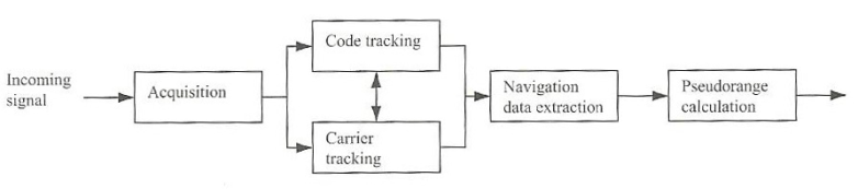
Figure 3.4 : Block Diagram of a GPS receiver.
2- Acquisition.
In order to receive and efficiently decode navigation data, the receiver must know which satellites are initially visible. This can be achieved using two common methods referred to as warm start and cold start. In a warm start, the receiver uses the information it has stored from the previous results and is able to compute which satellites are visible. In a cold start, the receiver has no stored information and has to search for the visible satellites. This process is called acquisition and aims at determining the visible satellites as well as the coarse values of the carrier frequency and the code phase of the satellite signals. Acquisition is quite time-consuming as it has to search through all possible satellites (all PRN sequences), all possible carrier frequencies taking into account the Doppler shift and all possible code phases of a given PRN sequence. As a result, a 2-dimensional search in frequency (Doppler shift) and time (code phase) is carried out for each PRN sequence. This process can be performed using a serial search acquisition, a parallel frequency space search acquisition or a parallel code phase search acquisition. These three commons methods have different characteristics regarding the execution time, their complexities and their accuracies. They will be briefly depicted in the three following subsections.
a- Serial Search Acquisition.
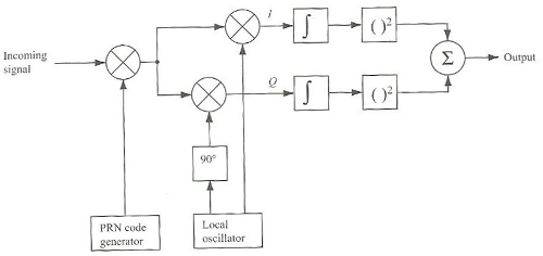
Figure 3.5 : Block Diagram - Serial Search Acquisition.
The serial search acquisition procedure is based on the C/A code correlation properties (see PART 2) according to which the cross correlation between two different C/A codes is really low and the autocorrelation is high only for zero lag. The algorithm is described just below.
The incoming signal is multiplied by a given C/A code with a certain code phase between 0 and 1022 chips. Then, the signal is mixed with a locally generated carrier signal to remove the carrier wave of the received signal. This generates an in-phase signal I and a quadrature signal Q. As the C/A code is modulated onto the I signal, one should only take into consideration the I signal. Nevertheless, the down-conversion is non-coherent. This means that the locally generated carrier wave used to down-convert the incoming signal is not in phase with the incoming carrier wave. As a consequence, the signal of interest is divided on both I and Q signals after down-conversion. Thus, it is necessary that one should use both of the I and Q signals. These I and Q signals are integrated over 1 ms which corresponds to the length of one C/A code. By doing so, one is correlating the incoming PRN sequence with the locally generated C/A code on both I and Q signals. The outputs of both I and Q signals are finally squared and added. The final result is compared to a threshold. If the threshold is exceeded, the frequency and code phase parameters used for the locally generated signals are correct for the PRN sequence that is considered. If the threshold is not exceeded, this could be due to several reasons that are listed just below:
- The locally generated PRN sequence is not the same as the one that is received, which means that the receiver is not configured to receive signals from the actually targeted satellite.
- The locally generated PRN sequence is the right one but its code phase does not match the incoming PRN sequence.
- The locally generated carrier wave does not have the same frequency as the incoming carrier wave because of the Doppler shift.
The GPS receiver cannot know the cause that leads to low correlation. It will therefore proceed using a two-dimensional search in frequency and time for each PRN sequence in order to find the right frequency and the right code phase for the PRN sequence that is considered. Considering that the Doppler shift is around ± 10 kHz, it is reasonable to take a frequency step of 500 Hz resulting in 41 frequencies around the theoretical L1 frequency. For each frequency, 1023 different code phases are tried for the PRN sequence that is considered (recall that one C/A code contains 1023 chips). The output is computed for all the pairs “frequency/code phase” and can be plotted on a 3D graph as shown on figures XX and XX. Then, the maximum value from all the possibilities is computed. If this maximum does not exceed the threshold, the PRN sequence for which the search has been done corresponds to a satellite that is not visible to the receiver and the search has to be carried out for another PRN sequence. If the maximum exceeds the threshold, the satellite is acquired with coarse values of its carrier frequency and code phase.
b- Parallel frequency space search acquisition.
The serial search acquisition implies to test every combination of frequencies and code phases of a given PRN sequence before being able to tell if the acquisition is successful or not. This process is really time-consuming. If the search procedure of one of the two parameters could be implemented in parallel, this would drastically decrease the acquisition time. The parallel frequency space search acquisition aims at automatically giving a coarse value of the frequency carrier of the incoming signal once the right code phase has been found. It is implemented as follows:

Figure 3.6 : Block diagram - Parallel frequency space search acquisition.
The incoming signal is multiplied by a given PRN sequence which code phase varies between 0 and 1022 chips. A Fourier transform is then used to assess the previous result in the frequency domain. The Fourier transform gives a complex signal and the output is obtained by taking the squared magnitude of this signal. When the locally generated PRN sequence corresponds to the satellite that is targeted and when the phase of this locally generated PRN sequence perfectly matches the one of the PRN sequence from the incoming signal, the output of the multiplication is illustrated as follows:
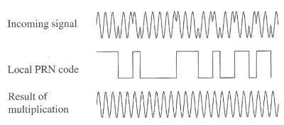
Figure 3.7 : Principle of Parallel frequency space search acquisition.
As such, the result corresponds to the carrier wave of the incoming signal. Consequently, the final output corresponds to the squared magnitude of the Fourier transform of a sine wave. In a nutshell, with a perfectly aligned PRN code of a visible satellite, the output displays a distinct peak in magnitude that corresponds to the real carrier frequency of the targeted satellite. This peak can be found using a threshold. When this threshold is exceeded, the satellite is acquired with coarse values of its carrier frequency and code phase. (insert image p 82 of the book)
c- Parallel code phase search acquisition.
The parallel frequency search acquisition implies to test every code phase among the 1023 possible options but eliminates the need to search through the 41 frequencies around the intermediate frequency of the received signal. The parallel code phase search acquisition allows parallelizing the code phase search. Thereby, the searching process only has to go through the 41 frequencies which drastically decreases the execution time.
The parallel code phase search acquisition takes advantage of the circular cross-correlation theorem that claims that the circular cross-correlation sequence between two finite sequences of length N and with periodic repetition can be obtained as the inverse transform of the product of the individual transforms:
Let z be the circular cross-correlation sequence between x and y that are two finite sequences of length N periodically repeated.

Let Z(k), X(k) and Y(k) respectively be the discrete N-point Fourier transforms of z(n), x(n) and y(n).
p=. Z(k) = X*(k)Y(k) where X*(k) is the conjugate of X(k)
Then:
p=. z(n) = invFFT(Z(k))
Such a property allows computing the cross-correlation of the incoming PRN sequence with a locally generated PRN sequence without the necessity of shifting its code phase. Consequently, only one PRN sequence has to be generated.
The block diagram of the parallel code phase search acquisition can be illustrated by the following figure:
3- Tracking.
a-

Figure 3.8 : from [2].

References :
[1] K. Borre, D. M. Akos, N. Bertelsen, P. Rinder, S. H. Jensen, A software-defined GPS and GALILEO receiver
[2] D. Kubrak, GNSS Signal Tracking Workshop, March 2016