
Work environment » History » Version 11
« Previous -
Version 11/26
(diff) -
Next » -
Current version
SANCHEZ, Eduardo, 03/25/2017 08:09 PM
Emulation architecture
So far, the data transmission and reception were simulated by LabView functions. In this section, the data modulation and demodulation are carried out by EL470 satellite modems. These modems are configured to operate in compliance with the DVB-S standard, i.e., performing data encapsulation, data encoding and QPSK modulation. Moreover, the satellite channel is implemented by using a vector signal transceiver (VST) integrated with a LabView programming environment.
Figure 1 shows the architecture used to evaluate the satellite channel emulator performance. Computer A generates IP packets that are send out to Modem A in order to communicate with Modem B. Modem A represents a hub modem which transmits a QPSK signal through the satellite link. Subsequently, the QPSK signal is processed by the VST which represents the satellite channel. According to a given Eb/No value, white gaussian noise is added to the signal, furthermore, the transmission through the VST output is delayed to emulate the typical satellite latency.
Finally, the delayed noisy signal is received by Modem B where the signal is demodulated, error correcting is performed and data is recovered in order to send to Modem B.
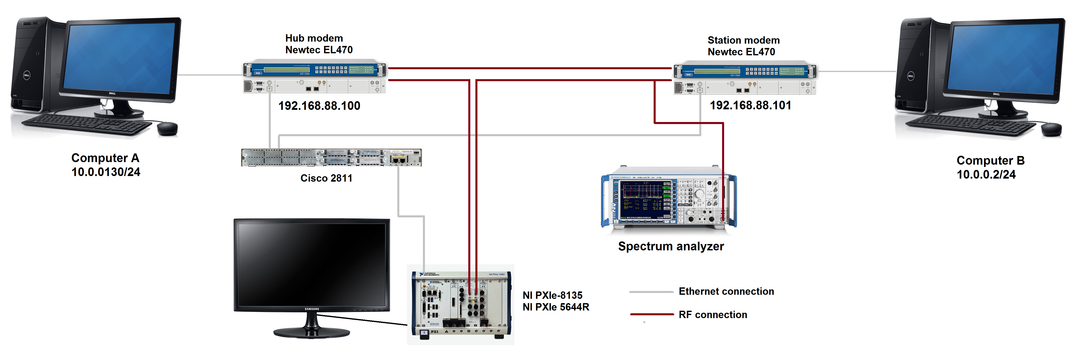
Figure 1. Emulation architecture
Device description
Modem configuration
The modems are configured for using DVB-S in a Single Channel Per Carrier (SCPC) scheme, i.e., the forward and return links uses DVB-S and there is no Demand Assigned Multiple Access (DAMA) since only one terminal is sending out data over the carrier.
The modem configuration interface is accessed via a web browser using the IP address as can be seen in Figures 2 and 3. The interface allows users to select the modulator/demodulator parameters such as the carrier frequency, the symbol rate, the modulation, etc.
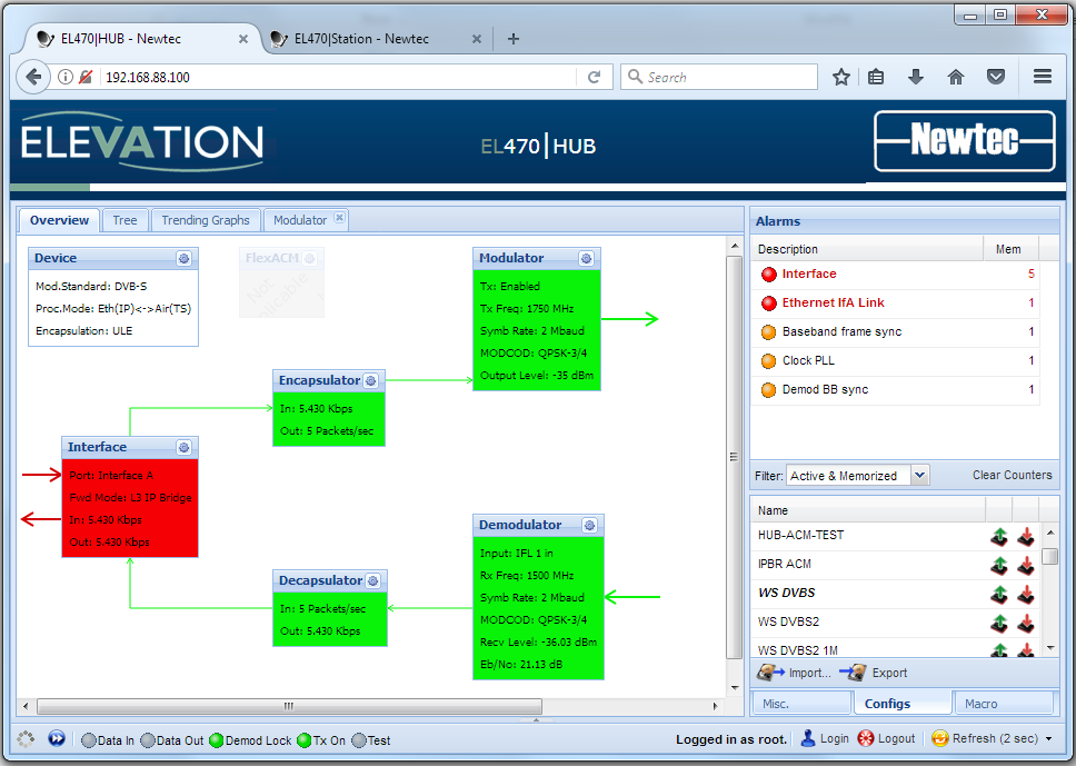
Figure 2. Modem A configuration
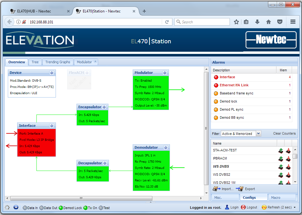
Figure 3. Modem B configuration
- Modulator
- Carrier frequency: 1.75 GHz
- Symbol rate: 2 Mbauds
- Modulation: QPSK
- Coding rate: ¾
- Roll-off factor: 0.35
- Output power: -35 dBm
- Demodulator
- Carrier frequency: 1.50 GHz
- Symbol rate: 2 Mbauds
- Modulation: QPSK
- Coding rate: ¾
- Roll-off factor: 0.20
- Output power: -35 dBm
- Modulator
- Carrier frequency: 1.50 GHz
- Symbol rate: 2 Mbauds
- Modulation: QPSK
- Coding rate: ¾
- Roll-off factor: 0.35
- Output power: -35 dBm
- Demodulator
- Carrier frequency: 1.75 GHz
- Symbol rate: 2 Mbauds
- Modulation: QPSK
- Coding rate: ¾
- Roll-off factor: 0.20
- Output power: -35 dBm
Furthermore, the configuration interface provides graphic tools to monitor the modem status. For instance, the IP throughput, the carrier-to-noise ratio at the demodulator input and the received output power are plotted as shown in Figure 4.
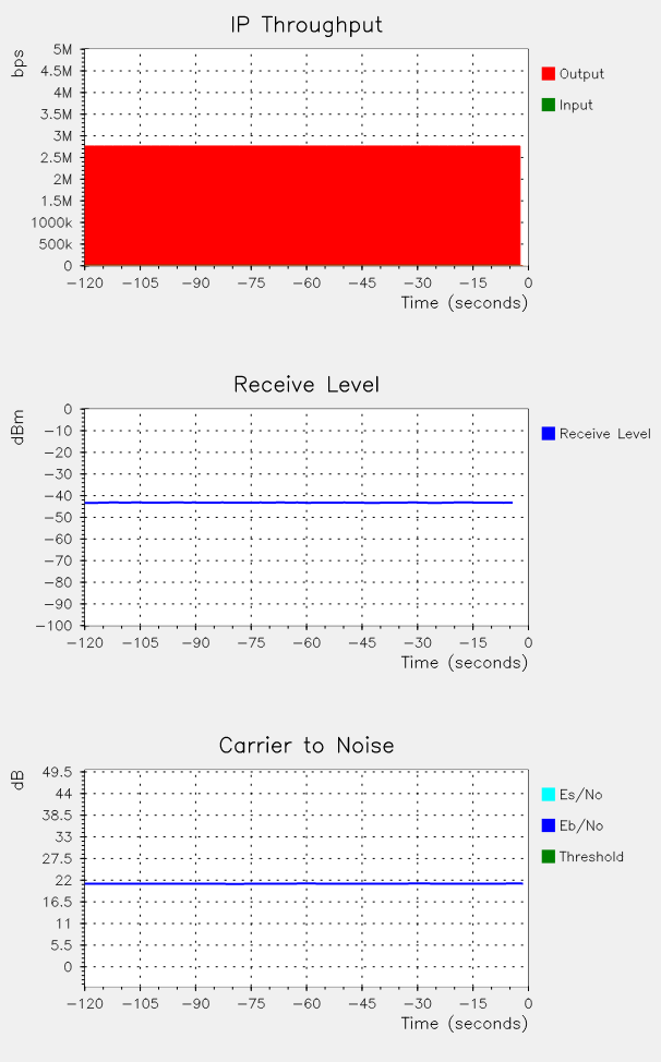
Figure 4. Modem status