Work environment » History » Version 20
« Previous -
Version 20/26
(diff) -
Next » -
Current version
ZHAI, Lili, 03/28/2017 10:19 AM
Emulation architecture
So far, the data transmission and reception were simulated by LabView functions. In this section, the data modulation and demodulation are carried out by EL470 satellite modems. These modems are configured to operate in compliance with the DVB-S standard, i.e., performing data encapsulation, data encoding and QPSK modulation. Moreover, the satellite channel is implemented by using a vector signal transceiver (VST) integrated with a LabView programming environment.
Figure 1 shows the architecture used to evaluate the satellite channel emulator performance. Computer A generates IP packets that are send out to Modem A in order to communicate with Modem B. Modem A represents a hub modem which transmits a QPSK signal through the satellite link. Subsequently, the QPSK signal is processed by the VST which represents the satellite channel. According to a given $Eb/No$ value, white gaussian noise is added to the signal, furthermore, the transmission through the VST output is delayed to emulate the typical satellite latency.
Finally, the delayed noisy signal is received by Modem B where the signal is demodulated, error correcting is performed and data is recovered in order to send to Modem B.

Figure 1. Emulation architecture
Device description
Newtec EL470
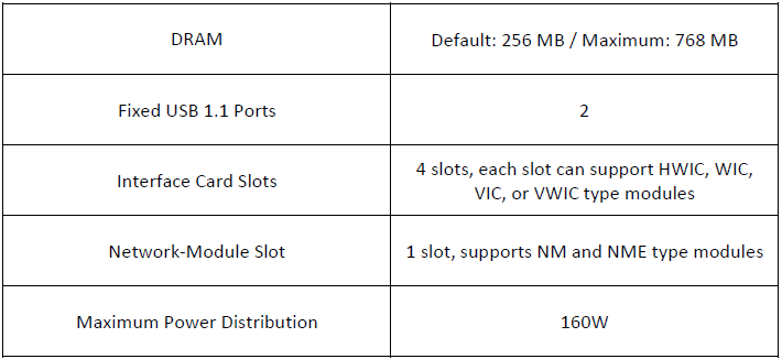
The modem EL470, which is accord with the DVB or DVBS2 standards, is one of the most advanced satellite modems. Its principal function is to transmit and receive the IP streams over satellite. Its advantages include the direct connection to IP network infrastructures via a single auto-switching Gigabit Ethernet interface and the possibility to use multiple encapsulation protocols. Its maximum rate can reach 133Mbit/s.
The main characteristics are shown in the following table:
Ethernet switch CISCO 2811
Cisco 2811 series integrated services routers are capable of grouping data, security, voice and wireless services into a readable system, providing adequate network performance for the wired or wireless connections.
The main characteristics are shown in the following table:

Table 2. Cisco2811 main characteristics
NI PXIe-8135
This embedded controller consists of a quad-core Intel Core i7-3610QE processor and all the I/O standarde. It integrates standard I/O features in a single unit by the compact packaging technology. Combining with other NI compatible chassis, it can be a completely compatible computer.
The main characteristics are shown in the following table:
NI PXle-5644R
A new type of instrumentation that assembles a vector signal generator and vector signal analyzer with FPGA-based real-time signal processing and control has been developed, and the NI PXIe-5644R vector signal transceivers are part of it. Thanks to this software-designed approach, a VST could have the flexibility of software defined radio architecture with RF instrument class performance.
The main characteristics are shown in the following table:
FSV signal and spectrum analyzer
The FSV signal and spectrum analyzer is widely used for signals to develop, product, install and service in the RF systems. It offers the digital modulation analysis for the measurements which can reach 160MHz analysis bandwidth.
The main characteristics are shown in the following table:
Modem configuration
The modems are configured for using DVB-S in a Single Channel Per Carrier (SCPC) scheme, i.e., the forward and return links uses DVB-S and there is no Demand Assigned Multiple Access (DAMA) since only one terminal is sending out data over the carrier.
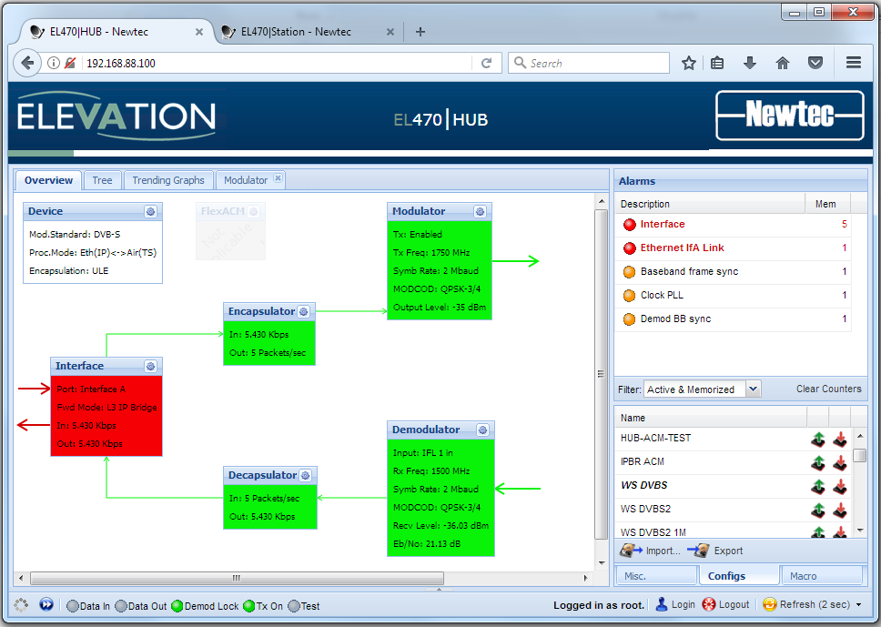
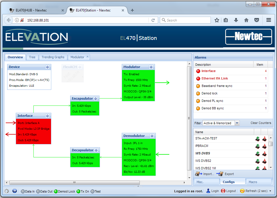
The modem configuration interface is accessed via a web browser using the IP address as can be seen in Figures 2 and 3. The interface allows users to select the modulator/demodulator parameters such as the carrier frequency, the symbol rate, the modulation, etc.

Figure 2. Modem A configuration

Figure 3. Modem B configuration
- Modulator
- Carrier frequency: 1.75 GHz
- Symbol rate: 2 Mbauds
- Modulation: QPSK
- Coding rate: ¾
- Roll-off factor: 0.35
- Output power: -35 dBm
- Demodulator
- Carrier frequency: 1.50 GHz
- Symbol rate: 2 Mbauds
- Modulation: QPSK
- Coding rate: ¾
- Roll-off factor: 0.20
- Output power: -35 dBm
- Modulator
- Carrier frequency: 1.50 GHz
- Symbol rate: 2 Mbauds
- Modulation: QPSK
- Coding rate: ¾
- Roll-off factor: 0.35
- Output power: -35 dBm
- Demodulator
- Carrier frequency: 1.75 GHz
- Symbol rate: 2 Mbauds
- Modulation: QPSK
- Coding rate: ¾
- Roll-off factor: 0.20
- Output power: -35 dBm
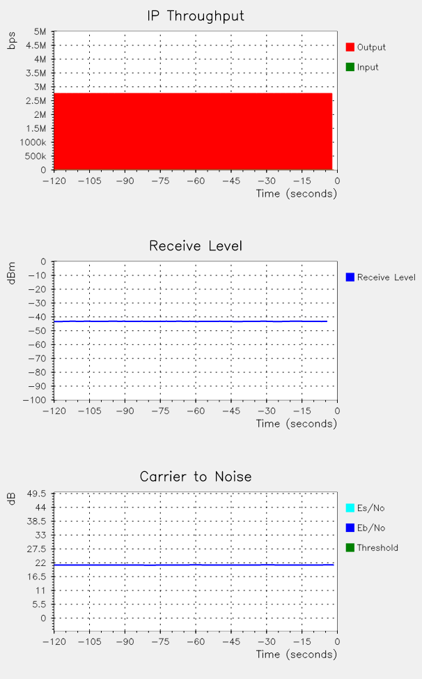
Furthermore, the configuration interface provides graphic tools to monitor the modem status. For instance, the IP throughput, the carrier-to-noise ratio at the demodulator input and the received output power are plotted as shown in Figure 4.

Figure 4. Modem status
