3 Moving from simulation to acquisition of real signals » History » Version 7
« Previous -
Version 7/9
(diff) -
Next » -
Current version
JANVIER, Thibault, 12/15/2015 11:45 AM
3. Moving from simulation to acquisition of real signals
Now that the signal analyser that has been implemented works with simulated signals, it is time to move to the acquisition of real satellite signals. To do so, the USRP has to be added as an RF front end in the labview code. This operation will add some modifications in the labview code.
3.1. Modifications due to the addition of the USRP
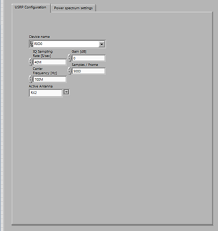
In fact, when we receive signals with the USRP, they are first expected to be down-converted to baseband, then filtered by a low-pass filter of 20 MHz-bandwidth and finally sampled. All these operations are controlled by the tab "USRP Configuration" in the "Analog" thumb index of the user interface. In the "Digital" thumb index, the configuration of the USRP is also available.

Figure 15: USRP Configuration
In the frequency domain, such operations are illustrated as follows:

Figure 16: Operations carried out by the USRP - Frequency domain illustration
The block we are using to compute the power spectrum calculates it between 0 and Fs/2. But because of the filtering, it is useless to compute the power spectrum over a range higher than 20 MHz. Thus, the maximum sampling rate will be set to 40 MHz. In order to display the power spectrum of the signal at the input of the USRP, a frequency shift is added to the power spectrum just computed to compensate the down-conversion. The most complicated is to find a signal with a low symbol rate because of this maximum sampling rate.
3.2. Modifications in the computation model of the signal-to-noise ratio
The satellite signals that are received are not as simple signals as sine waves. They might not be cyclostationary and therefore, their powers cannot be computed using their autocorrelation functions. As a consequence, the power of the useful received signal will be approximated by the maximum power that is detected in its frequency band. Likewise, the power of the noise will be measured by the maximum power that is detected in the noise floor of the system. As a result, we need to measure the power of the signal and the power of the noise with two different carrier frequencies of the USRP. The problem is that we can’t do these two computations at the same time. So we first need to launch the program with a carrier frequency corresponding to the noise (being in the tab “Power Spectrum Noise”) and after we launch it again with the carrier frequency of the signal (being in the tab “Power Spectrum Signal”).
Indeed if we set the carrier frequency of the USRP centered on our signal, we just have to do a peak detection to measure the power of the signal plus the noise. Then we have the power of the noise in taking a carrier frequency completely out the bandwidth of the satellite. Now we have the power of the noise and the power of the signal so we can easily compute the signal to noise ratio (SNR).
