|
NavigationData.PNG (68.9 KB)
NavigationData.PNG |
|
COLIN, Tony, 03/19/2016 03:55 PM
|
|
|
Localization.PNG (73.7 KB)
Localization.PNG |
|
COLIN, Tony, 03/19/2016 03:55 PM
|
|
|
003.PNG (173 KB)
003.PNG |
|
COLIN, Tony, 03/19/2016 04:37 PM
|
|
|
Preamble1.PNG (10.6 KB)
Preamble1.PNG |
|
COLIN, Tony, 03/19/2016 09:51 PM
|
|
|
Preamble2.PNG (13.5 KB)
Preamble2.PNG |
|
COLIN, Tony, 03/19/2016 09:51 PM
|
|
|
SatPos.PNG (72.2 KB)
SatPos.PNG |
|
COLIN, Tony, 03/19/2016 09:51 PM
|
|
|
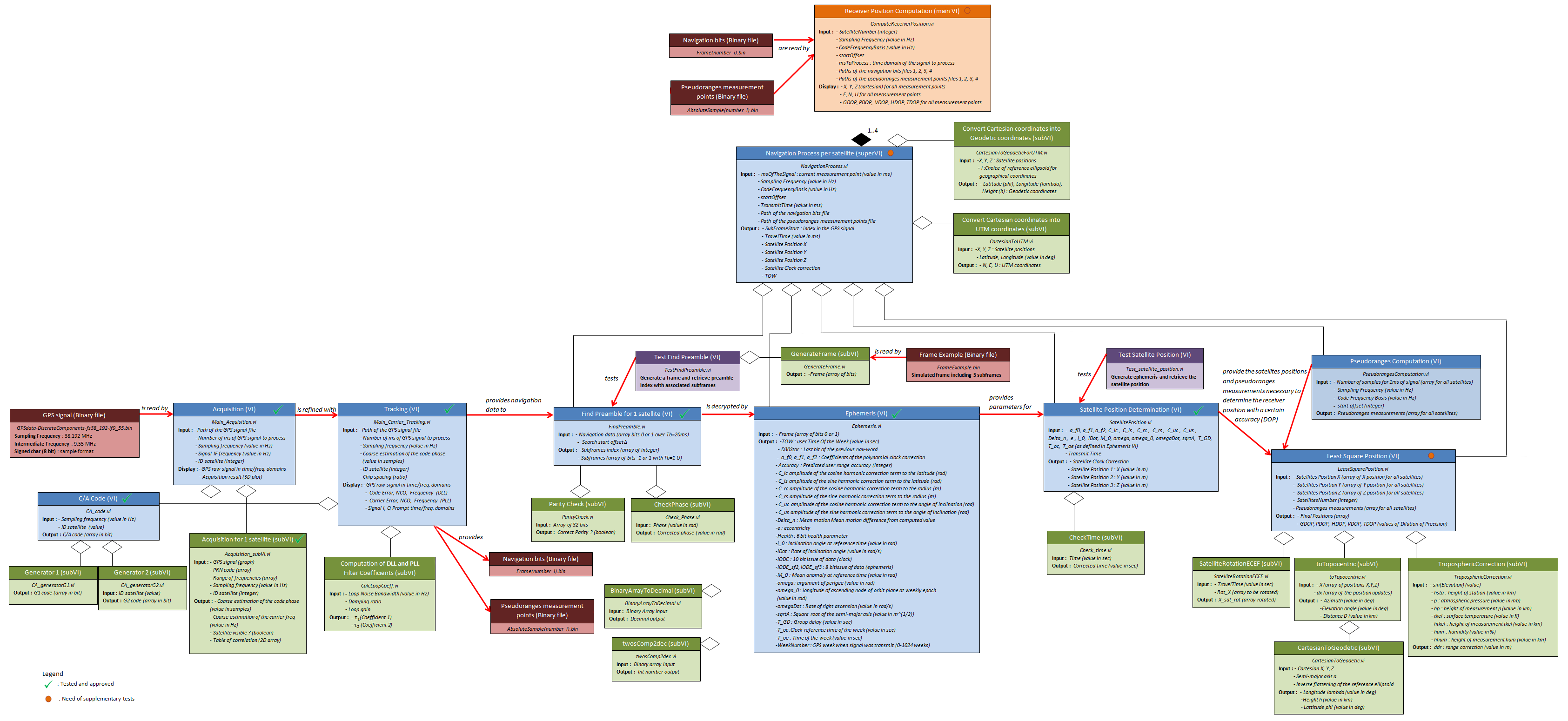
UMLDiagram.png (370 KB)
UMLDiagram.png |
|
COLIN, Tony, 03/22/2016 11:54 PM
|
|
|
UMLDoverview.PNG (124 KB)
UMLDoverview.PNG |
|
COLIN, Tony, 03/22/2016 11:57 PM
|
|
|
Acquisition.PNG (49.6 KB)
Acquisition.PNG |
|
COLIN, Tony, 03/23/2016 12:13 AM
|
|
|
Receiver.PNG (70.3 KB)
Receiver.PNG |
|
COLIN, Tony, 03/23/2016 12:13 AM
|
|
|
Track.PNG (43.9 KB)
Track.PNG |
|
COLIN, Tony, 03/23/2016 12:13 AM
|
|
|
SnapAcquisition.PNG (55.6 KB)
SnapAcquisition.PNG |
|
COLIN, Tony, 03/23/2016 01:00 AM
|
|
|
SnapAcquisitionSub.png (91.7 KB)
SnapAcquisitionSub.png |
|
COLIN, Tony, 03/23/2016 01:00 AM
|
|
|
SnapCalcLoopCoeff.PNG (10.2 KB)
SnapCalcLoopCoeff.PNG |
|
COLIN, Tony, 03/23/2016 01:00 AM
|
|
|
SnapBinaryArrayToDecimal.PNG (19.7 KB)
SnapBinaryArrayToDecimal.PNG |
|
COLIN, Tony, 03/23/2016 01:00 AM
|
|
|
SnapCartesianToGeodetic.png (99.2 KB)
SnapCartesianToGeodetic.png |
|
COLIN, Tony, 03/23/2016 01:00 AM
|
|
|
SnapCheckPhase.PNG (19.7 KB)
SnapCheckPhase.PNG |
|
COLIN, Tony, 03/23/2016 01:00 AM
|
|
|
SnapCheckTime.PNG (14.3 KB)
SnapCheckTime.PNG |
|
COLIN, Tony, 03/23/2016 01:00 AM
|
|
|
SnapSatelliteRotationECEF.PNG (18.6 KB)
SnapSatelliteRotationECEF.PNG |
|
COLIN, Tony, 03/23/2016 01:00 AM
|
|
|
SnapParityCheck.png (116 KB)
SnapParityCheck.png |
|
COLIN, Tony, 03/23/2016 01:00 AM
|
|
|
SnapTest_satellite_position.PNG (56.8 KB)
SnapTest_satellite_position.PNG |
|
COLIN, Tony, 03/23/2016 01:00 AM
|
|
|
SnapTestFindPreamble.PNG (9.73 KB)
SnapTestFindPreamble.PNG |
|
COLIN, Tony, 03/23/2016 01:10 AM
|
|
|
SnapCartesianToGeodeticForUTM.png (73.3 KB)
SnapCartesianToGeodeticForUTM.png |
|
COLIN, Tony, 03/23/2016 01:10 AM
|
|
|
SnapTracking.png (188 KB)
SnapTracking.png |
|
COLIN, Tony, 03/23/2016 01:11 AM
|
|
|
SnapTwosComp2dec.PNG (12.3 KB)
SnapTwosComp2dec.PNG |
|
COLIN, Tony, 03/23/2016 01:11 AM
|
|
|
SnaptoTopocentric.png (52.6 KB)
SnaptoTopocentric.png |
|
COLIN, Tony, 03/23/2016 01:11 AM
|
|
|
SDR_GPS_Receiver.PNG (12.7 KB)
SDR_GPS_Receiver.PNG |
|
JANVIER, Thibault, 03/23/2016 09:26 AM
|
|
|
PRN_sequence.PNG (20.3 KB)
PRN_sequence.PNG |
|
JANVIER, Thibault, 03/23/2016 09:38 AM
|
|
|
SnapCACode.png (45.1 KB)
SnapCACode.png |
|
COLIN, Tony, 03/23/2016 10:06 AM
|
|
|
SnapCartesianToUTM.png (314 KB)
SnapCartesianToUTM.png |
|
COLIN, Tony, 03/23/2016 10:06 AM
|
|
|
SnapFindPreamble.png (123 KB)
SnapFindPreamble.png |
|
COLIN, Tony, 03/23/2016 10:06 AM
|
|
|
SnapEphemeris.png (200 KB)
SnapEphemeris.png |
|
COLIN, Tony, 03/23/2016 10:06 AM
|
|
|
SnapG1.PNG (39.7 KB)
SnapG1.PNG |
|
COLIN, Tony, 03/23/2016 10:06 AM
|
|
|
SnapGenerateFrame.png (20 KB)
SnapGenerateFrame.png |
|
COLIN, Tony, 03/23/2016 10:06 AM
|
|
|
SnapNavigationProcess.png (101 KB)
SnapNavigationProcess.png |
|
COLIN, Tony, 03/23/2016 10:06 AM
|
|
|
SnapLeastSquare.png (161 KB)
SnapLeastSquare.png |
|
COLIN, Tony, 03/23/2016 10:06 AM
|
|
|
SnapPseudoranges.PNG (20.1 KB)
SnapPseudoranges.PNG |
|
COLIN, Tony, 03/23/2016 10:06 AM
|
|
|
SnapReceiver.png (258 KB)
SnapReceiver.png |
|
COLIN, Tony, 03/23/2016 10:06 AM
|
|
|
SnapG2.png (64.6 KB)
SnapG2.png |
|
COLIN, Tony, 03/23/2016 10:12 AM
|
|
|
SnapSatellitePosition.png (151 KB)
SnapSatellitePosition.png |
|
COLIN, Tony, 03/23/2016 10:12 AM
|
|
|
Loss_acquisition.PNG (671 Bytes)
Loss_acquisition.PNG |
|
JANVIER, Thibault, 03/23/2016 10:16 AM
|
|
|
Acquisition_Duration.PNG (7 KB)
Acquisition_Duration.PNG |
|
JANVIER, Thibault, 03/23/2016 10:27 AM
|
|
|
Main_Acquisition_1.PNG (67.4 KB)
Main_Acquisition_1.PNG |
|
JANVIER, Thibault, 03/23/2016 10:59 AM
|
|
|
Main_Acquisition_2.PNG (125 KB)
Main_Acquisition_2.PNG |
|
JANVIER, Thibault, 03/23/2016 10:59 AM
|
|
|
Table_PLL_DLL_discriminators.PNG (14.1 KB)
Table_PLL_DLL_discriminators.PNG |
|
JANVIER, Thibault, 03/23/2016 11:21 AM
|
|
|
ECEF.png (22.5 KB)
ECEF.png |
|
COLIN, Tony, 03/23/2016 11:55 AM
|
|
|
GeodeticSphere.PNG (65.9 KB)
GeodeticSphere.PNG |
|
COLIN, Tony, 03/23/2016 11:55 AM
|
|
|
RxyRealFrame.PNG (30.9 KB)
RxyRealFrame.PNG |
|
COLIN, Tony, 03/23/2016 11:55 AM
|
|
|
UTMzones.jpg (203 KB)
UTMzones.jpg |
|
COLIN, Tony, 03/23/2016 11:55 AM
|
|
|
Main_Tracking_1.PNG (73.6 KB)
Main_Tracking_1.PNG |
|
JANVIER, Thibault, 03/23/2016 12:00 PM
|
|
|
Main_Tracking_2.PNG (63.3 KB)
Main_Tracking_2.PNG |
|
JANVIER, Thibault, 03/23/2016 12:00 PM
|
|
|
Main_Tracking_3.PNG (54.8 KB)
Main_Tracking_3.PNG |
|
JANVIER, Thibault, 03/23/2016 12:00 PM
|
|
|
Main_Tracking_4.PNG (74.3 KB)
Main_Tracking_4.PNG |
|
JANVIER, Thibault, 03/23/2016 12:00 PM
|
|
|
SnapTropospheric.png (186 KB)
SnapTropospheric.png |
|
COLIN, Tony, 03/23/2016 12:01 PM
|
|
