
PART3 » History » Version 40
« Previous -
Version 40/83
(diff) -
Next » -
Current version
COLIN, Tony, 03/22/2016 11:57 PM
PART 5 : Implementation.
- Table of contents
- PART 5 : Implementation.
.......................
1 - Starting point.
a - Receiver scheme and milestones.
.......
b - Quid about LabVIEW.
.......
Input : GPS signal of sampling frequency 38.192 MHz at intermediate frequency 9.55 MHz from CD [1] under GNSS_signal_records/GPSdata-DiscreteComponents-fs38_192-if9_55.bin
c - Local C/A code generation.
Generation : CA_code.vi with subVI CA_generatorG1.vi CA_generatorG2.vi
2 - Acquisition.
Justification acquisition method in terms of accuracy and time execution
Justification of the step of 500Hz
Methods to avoid the data bit transition while running acquisition
Frequency refine is needed for the PLL of the tracking to converge
Definition of the threshold and how it is implemented
.......
...........
3 - Tracking.
.......
...........
![]()
4 - Navigation Data decoding.
See the UML Diagram of Section 4 under : NavigationData.PNG.
a - Delimiting subframes.
The files involved are :
- FindPreamble.vi
- TestFindPreamble.vi
- GenerateFrame.vi
- ParityCheck.vi
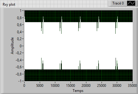
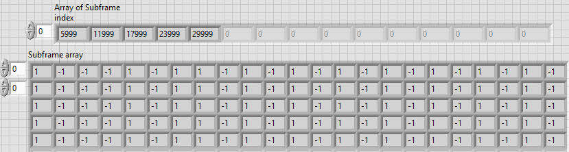
Figure 5. : Cross-correlation between navigation frame and local preamble. Figure 5. : Subframes with index of delimitation.
b- Decoding ephemeris and information within the frame.
The files involved are :
- Ephemeris.vi
- BinaryArrayToDecimal.vi
- twosComp2dec.vi
- ParityCheck.vi
- TestEphemeris.vi
5 - Localization computation.
See the UML Diagram of Section 5 under : Localization.PNG
a - Satellite position.
The files involved are :
- SatellitePosition.vi
- TestSatellitePosition.vi
- Check_time.vi
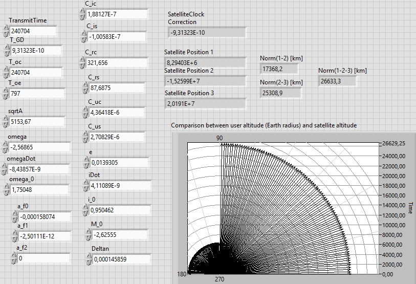
Figure 5. : Interface with ephemeris as input and illustration of the satellite position.
b - Pseudoranges.
The file involved is :
PseudorangesComputation.vi
c - Least Square solution for position determination.
The files involved are :
- LeastSquarePosition.vi
- SatelliteRotationECEF.vi
- toTopocentric.vi
- CartesianToGeodetic.vi
- TroposphericCorrection.vi
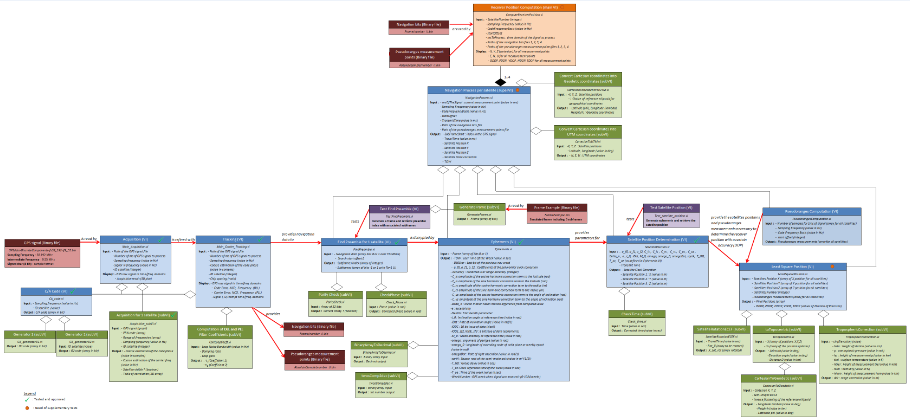
6 - Complete UML Diagram of the receiver.
The UML diagram is available under : UMLDiagram.png
Here is a small overview of the structure :
References :
[1] K. Borre, D. M. Akos, N. Bertelsen, P. Rinder, S. H. Jensen, A software-defined GPS and GALILEO receiver