
Receiving antenna building » History » Version 11
« Previous -
Version 11/62
(diff) -
Next » -
Current version
SCHNEIDER, Joris, 03/23/2017 10:56 PM
Previous : Receiving antenna design
Receiving antenna building
List of components
Assembly
Testing
In order to ensure the fact that the antenna is functioning well, we made several tests.
At first, we had to ensure that the cables will really bring the phase shift of a Pi/2 between opposite dipoles. To do so, we plugged in the cables to a signal generator. We generated a sine signal at 137MHz and observed on an oscilloscope the signal at the output of two cables which have a different length as explained in the design part. Here you can find pictures of the signal generator and the observed signal at the ouput.
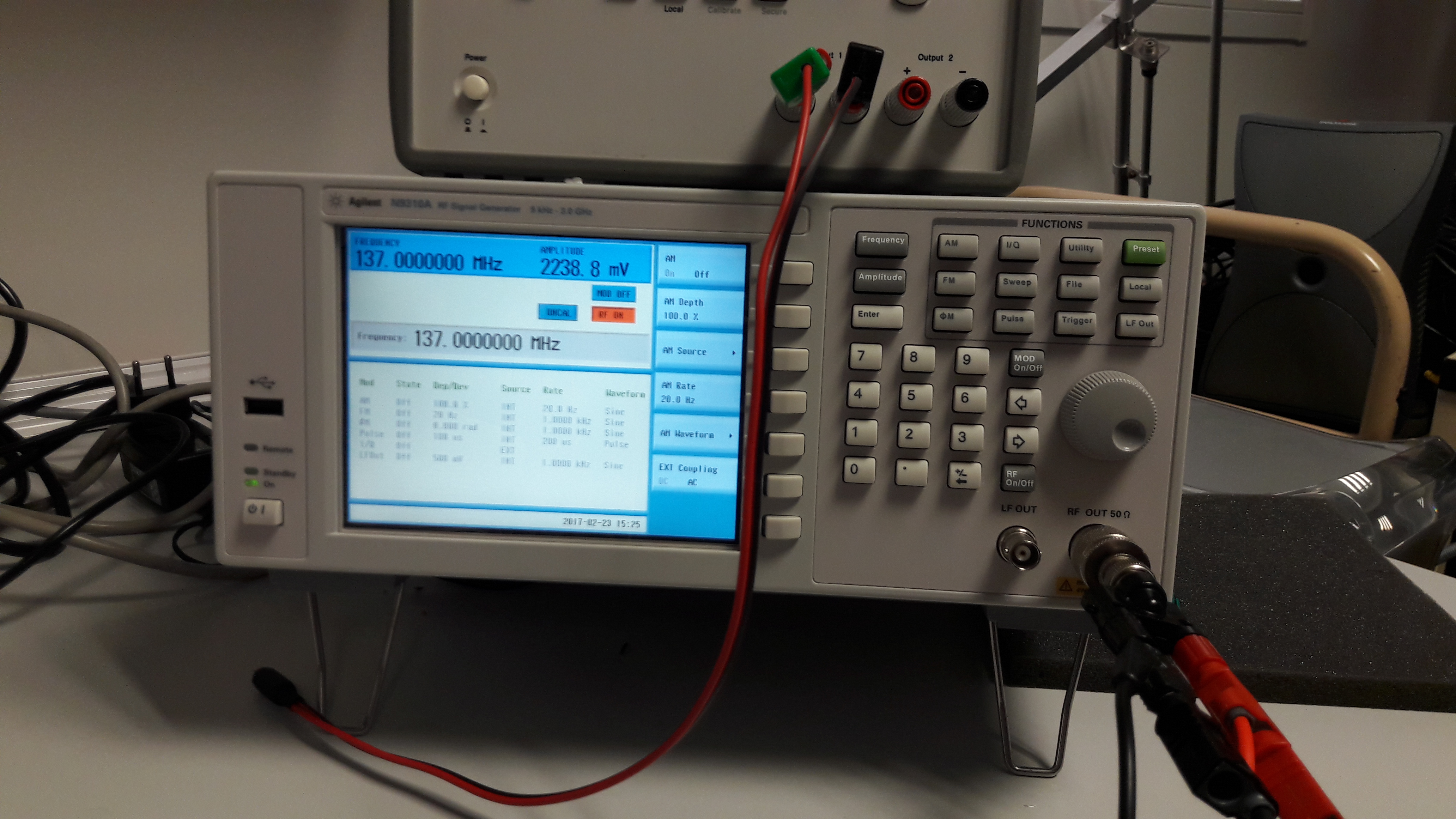
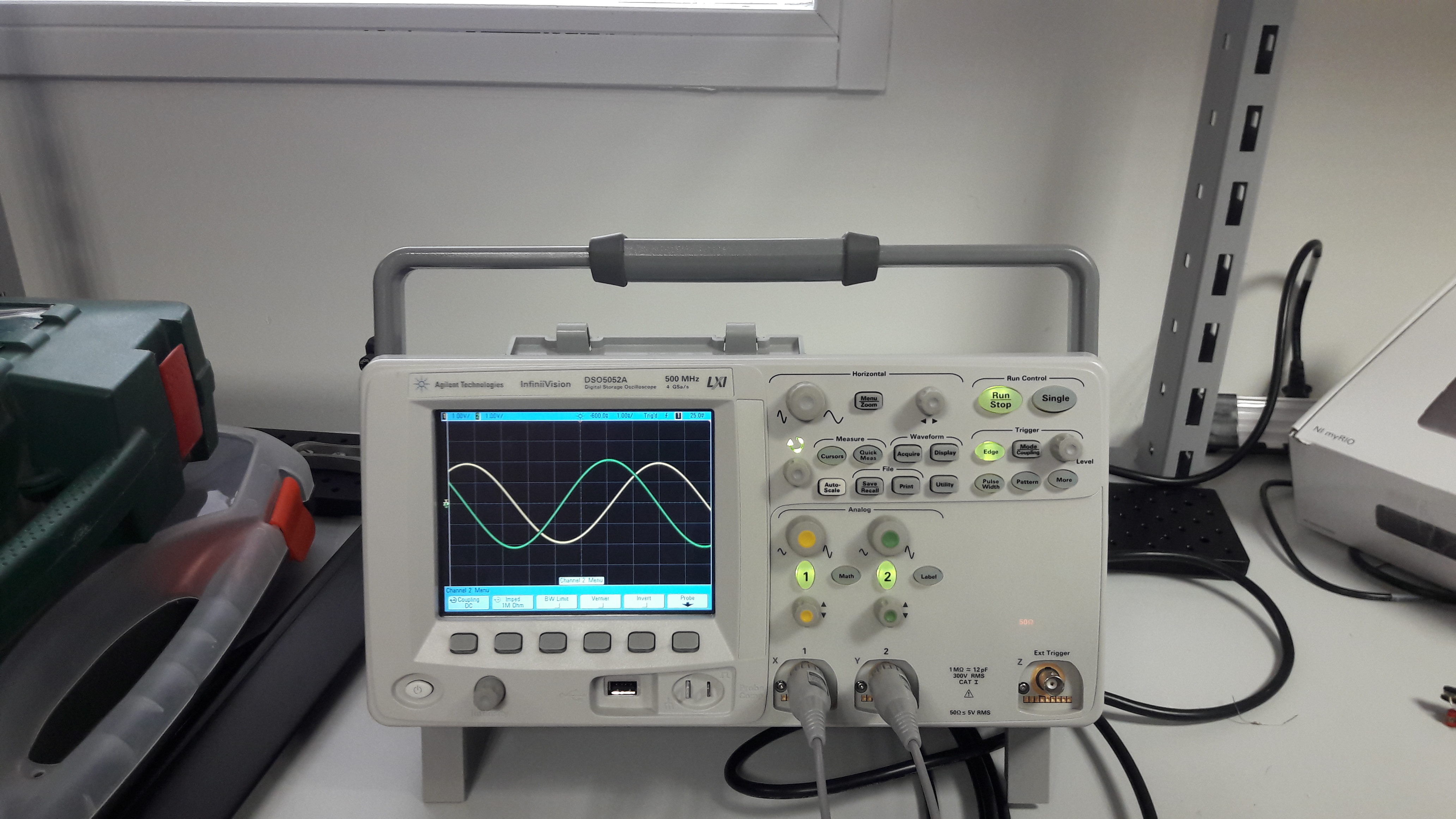
We see that the phase shift between the two cables is about Pi/2.
Then, at each step during the assembly, we tested each connection with a multimeter in order to ensure that all connections are correctly done.
Validation
Even if we tested the cables and all the connections, we need to make sure the antenna is really able to receive APT signals. So, we plugged in the coaxial cable of our antenna to a radio receiver. As an APT signal is audible once demodulated in frequency, we can determine easily if the antenna is correctly working or not. To know when a satellite pass above Toulouse, we used a tracker software called WXTrack. Thanks to this software, we are able to know when each NOAA satellite will be visible.
To validate our antenna, we only had to turn on the radioreceiver to the correct frequency depending on the satellite which is available and listen to the signal directly at the output of the receiver. Here is the radio receiver configured on the NOAA 19 frequency (137.1MHz).

During our tests, we could correctly hear the specific signal. To have an idea, an example of audible APT signal is available in the files list (florida.wav). You can download it to hear the APT signal.
Next : [[]]