Receiving antenna building » History » Version 54
« Previous -
Version 54/62
(diff) -
Next » -
Current version
QUERE, Antoine, 03/27/2017 10:50 AM
Previous : Receiving antenna design Next : APT images reception
Receiving antenna building
List of components
Here is the main material needed to build the double cross antenna:
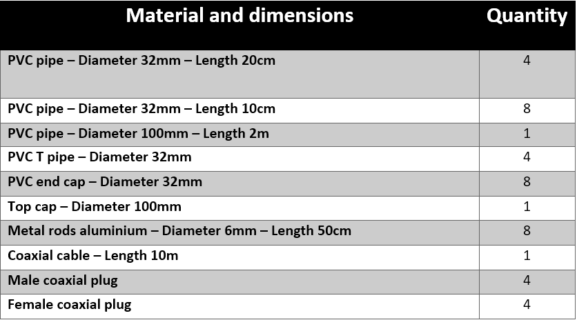
All these materials are available in any supermarket with a plumbing section. The aluminium rods can be replaced by any other conductive material. Moreover, here we decided to use Male/female coaxial plugs in order to be able to remove each side of the antenna as we wanted a removable antenna that is easier to move and to store.
Additionally to these materials, some specific tools and softwares are needed to be able to decode the APT signals:- Radio receiver
- WXTrack and WXtoImg softwares
- LabView software
Assembly
Once all the materials have been bought, we have started to build the antenna.
Firstly, we have sawed the four 1 meter rods in two to obtain our four dipoles. Indeed, our dipole is composed by a pair of metal rod.
Secondly, we have cut four pieces of 32mm diameter PVC pipe with a length of 20cm to create the four branches of the double cross antenna.
Then, always with the 32mm diameter PVC pipe, we have sawed eight pieces for the T pipe PVC to support the dipoles.
After that, we have pasted four PVC pipe support. To the 100 mm diameter PVC pipe, which is the mast of the antenna. These elements support and connect the branches to the mast. Once the glue has dried, we have drill holes in the mast for passing the cables to the dipoles via the different branches.
After this last operation, we have cut the cable as we have presented in the Receiving antenna design polarization part. Thus we have had two cable with a length of 1.44m for the north and south side and 1.80m for the east and west side. The difference of length is a proportional to a quarter wavelength in respect of the velocity factor of the cable RG58U.
We have made the choice to have a removable antenna. Thus, we need to use male/female coaxial plugs in order to part the cable. We have stripped the cable for separate the copper core and the woven copper shield. The copper core needs to go in the center of the plug and be isolated from the copper shield.
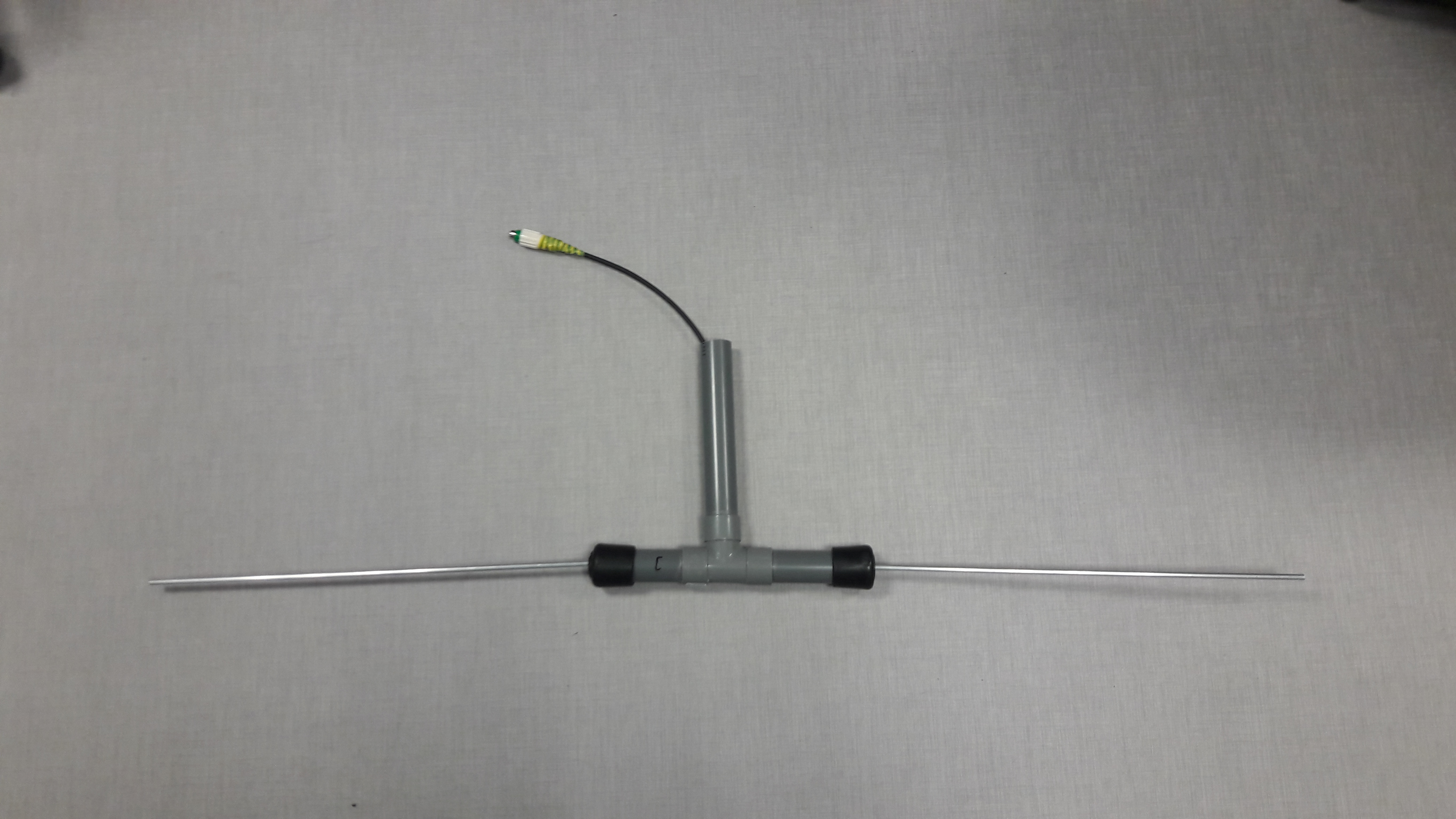
The next step was the connections between the cable and the dipoles. We have started by strip the cable for separate the copper core and the woven copper shield. As we have explained earlier, one part of the dipole needs to be connected with the copper core and the other part with the copper shield. Once this two elements have been separated, we have twisted the copper shield and connected to the down part of the dipole with the help of screw terminal. We have repeated this operation with the up part of the dipole and the copper core. These connections have been attached to metal support by an adhesive with the target to reinforce the strength of the links. We have placed all of these components in the Tee pipe and add rubber top cap at the opposite part of the Tee to support and axe the both part of the dipole as the following picture depict.
One of the last tasks, is to link the cable of each branch in one calbe. The connections between these cables as the same as we have illustrated in the Receiving antenna design polarization part. Thus, we have made the connections between cooper core and cooper core, cooper core and cooper shield, and cooper shield and cooper shield with the help of screw terminal as we have done previously. Once all cables have been linked we reinforce it with adhesive. The following pictures represent the final cable which will be present in the mast.

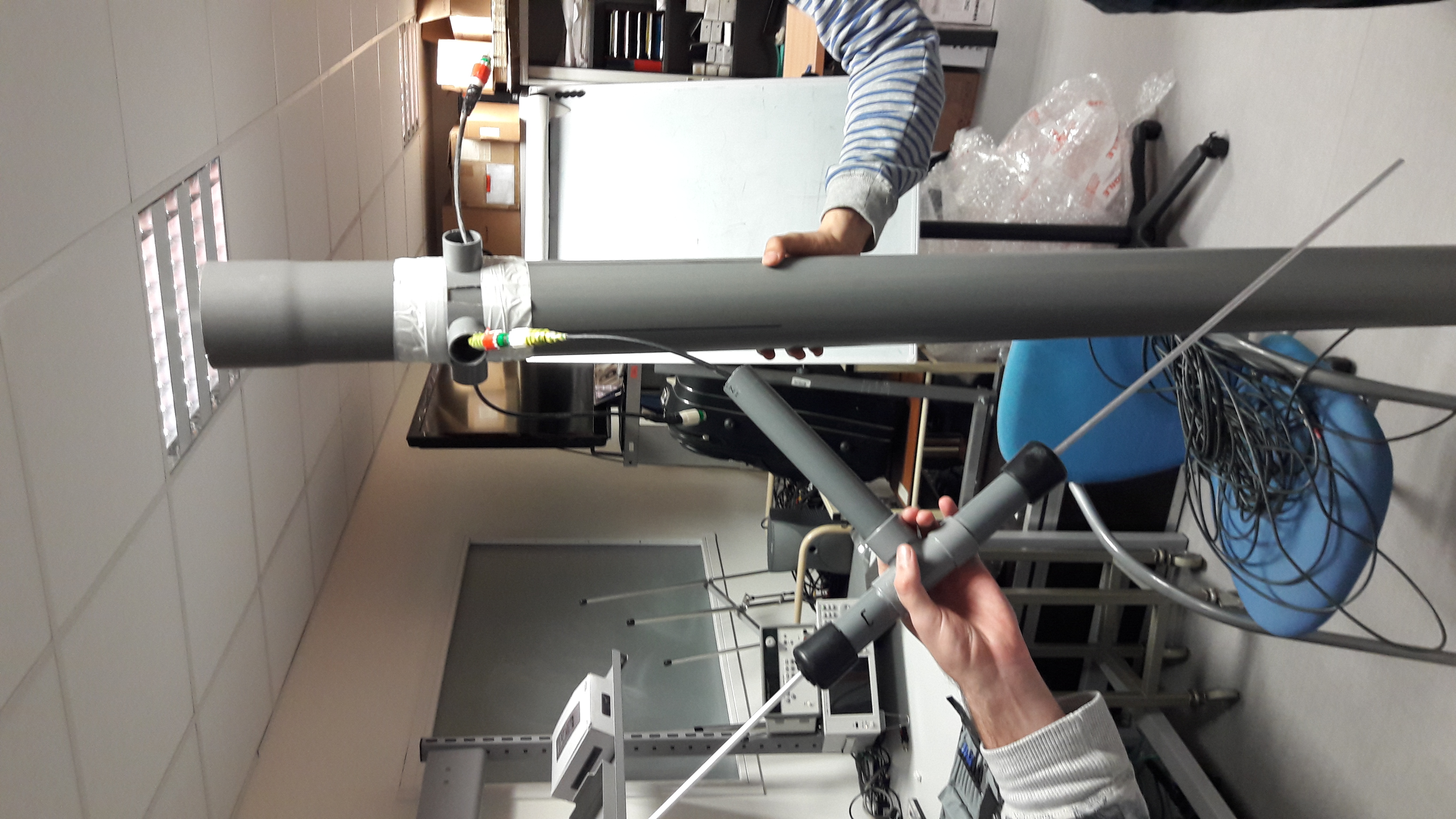
After ten hours of building, we have connected the different cables with the plugs, reatached the branches to the mast as presented below and then rotate the dipole with an angle of 30°.
The antenna is now finished and we have placed it on the roof of the lab building. The antenna stands up with a help of a support where we have had flagstone to be sure that it will not fall in case of severe weather.
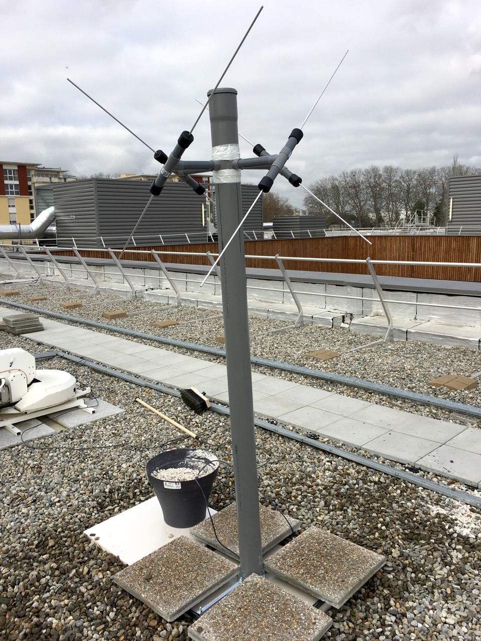
We can now testing our antenna and validate it to be sure that we can receive the APT images.
Testing
In order to ensure the fact that the antenna is functioning well, we made several tests.
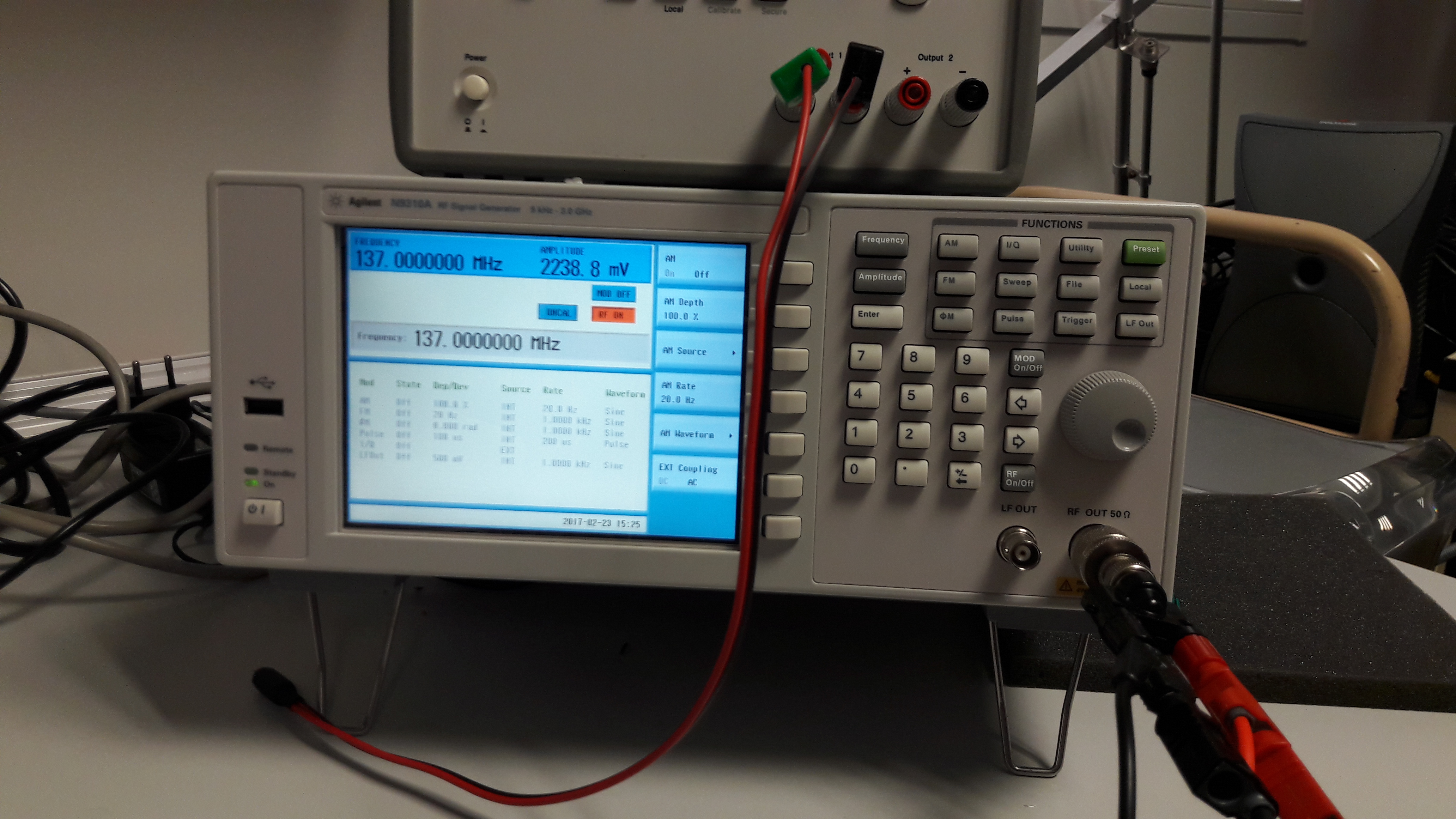
At first, we had to ensure that the cables will really bring the phase shift of a Pi/2 between opposite dipoles due to the difference a quarter wavelength. To do so, we plugged in the cables to a signal generator. We generated a sine signal at 137MHz and observed on an oscilloscope the signal at the output of two cables which have a different length as explained in the design part. Here you can find pictures of the signal generator and the observed signal at the ouput.
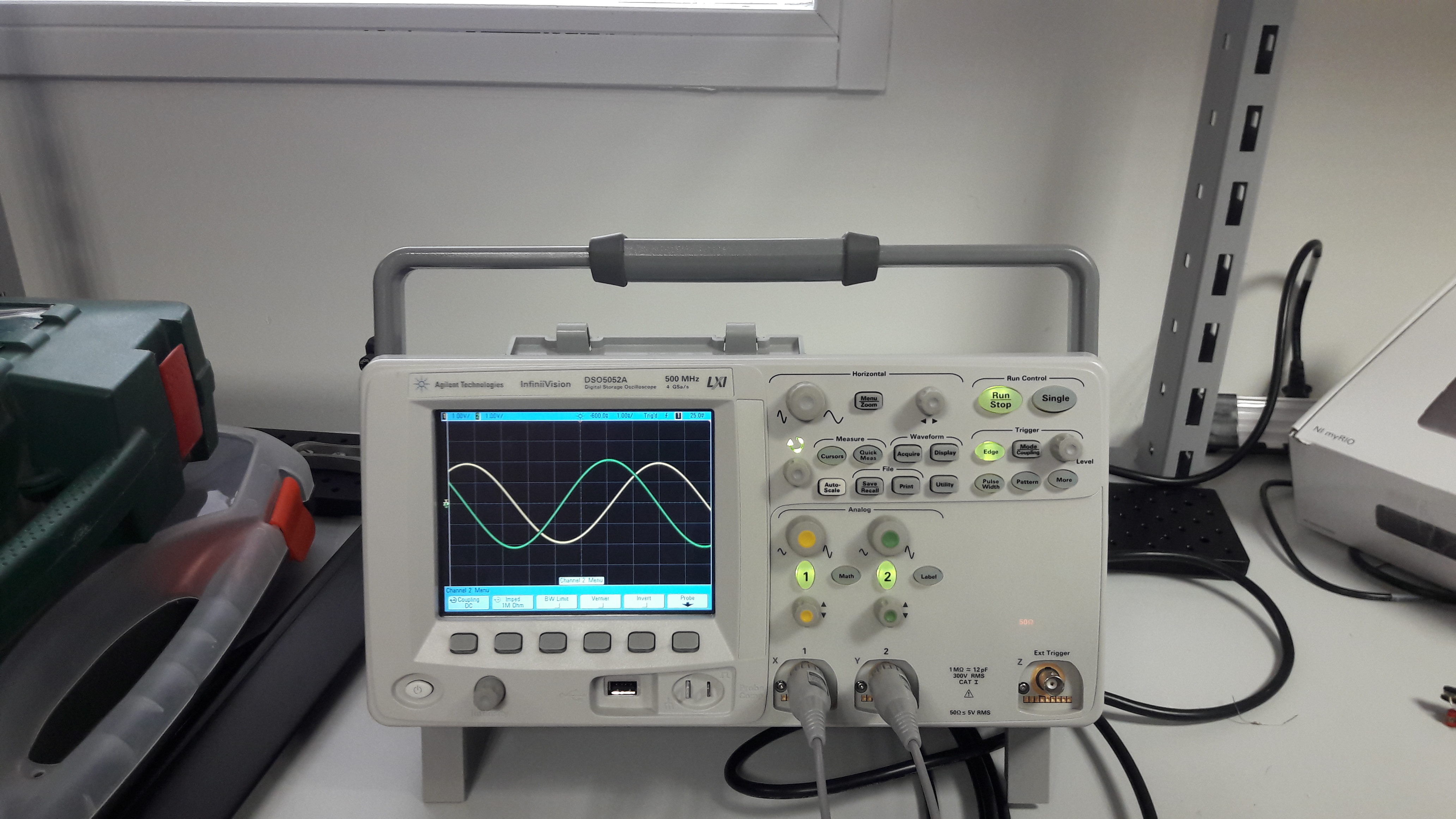
We see that the phase shift between the two cables is about Pi/2. It allows to confirm that our cables are perfectly sized.
Then, at each step during the assembly, we tested each connection with a multimeter in order to ensure that all connections are correctly done.
Validation
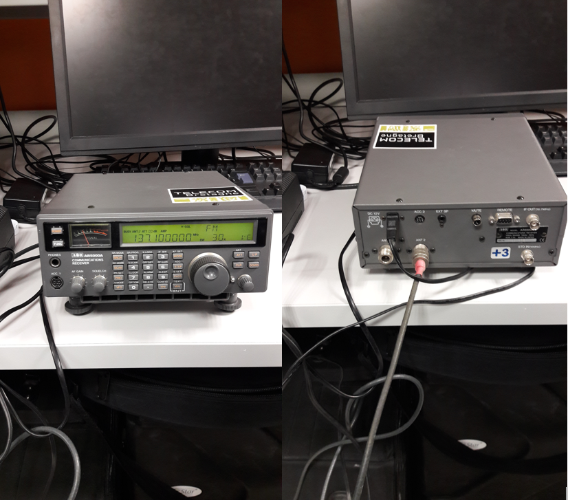
Even if we tested the cables and all the connections, we need to make sure the antenna is really able to receive APT signals. So, we plugged in the coaxial cable of our antenna to a radio receiver. As an APT signal is audible once demodulated in frequency, we can determine easily if the antenna is correctly working or not. To know when a satellite pass above Toulouse, we used a tracker software called WXTrack. Thanks to this software, we are able to know when each NOAA satellite will be visible.
To validate our antenna, we only had to turn on the radioreceiver to the correct frequency depending on the satellite which is available and listen to the signal directly at the output of the receiver. Here is the radio receiver configured on the NOAA 19 frequency (137.1MHz).
During our tests, we could correctly hear the specific signal. To have an idea, an example of audible APT signal is available in the files list (florida.wav). You can download it to hear the APT signal.
Previous : Receiving antenna design Next : APT images reception
