Previous : System and signal description Next : Receiving antenna design
Receiving antenna choice
In this part of our project, we will build a receiving antenna so as to collect information from weather satellites. We must choose our antenna according to the signal characteristics such that:
• The type of radio-frequency signal polarization to receive: it defines the orientation of the radio waves in space and the receiving antenna polarization have to fit the one at the emitter in order to maximize the signal strength.
• The gain provided by the antenna must be sufficient in the satellite direction to be able to extract the signal: the antenna should increase the signal strength to improve the image quality.
Moreover, as the frequency of APT signals is between 137MHz and 138MHz, we must consider the Faraday rotation. This phenomenon is effective for frequencies lower than 5Ghz in the ionosphere. It transforms a linear polarization to a circular one. Consequently, the emitter on the NOAA satellite uses a Right-Hand Circular Polarization (RHCP) to avoid this depolarization. It means our receiver must also use the same polarization.
Following this property, we can consider two main antenna types. Either we can use a directional antenna or an omnidirectional one.
Directional antennas
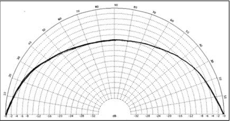
Considering directional ones, Yagi antenna should fulfil the polarization property for instance. The principal benefit is that its radiation pattern is more focused in one direction, so that it can provides a larger gain than omnidirectional antennas, taking into account we use a tracking system. Here is the radiation pattern of this antenna:

Directional antenna and its radiated pattern
Even if we could have better performances due to a larger gain, the use of such a system is more complex and costly. Moreover, some previous studies on APT receivers have shown that we can achieve sufficient results with omnidirectional antennas which are less complex and less costly to build. Consequently, we will focus on these systems.
Omnidirectional antennas
Requirements
In order to define our needs in gain defined by a radiation pattern, we will present how our system will exactly perform.
• Firstly, the antenna will be fixed on the roof to be in a line of sight condition. In the opposite case, we could have used a radiation pattern with high gain on the bottom as the reflected signal is less powerful than the direct one. So, in the line of sight condition, we can tolerate a lower gain on the bottom of our radiation pattern.
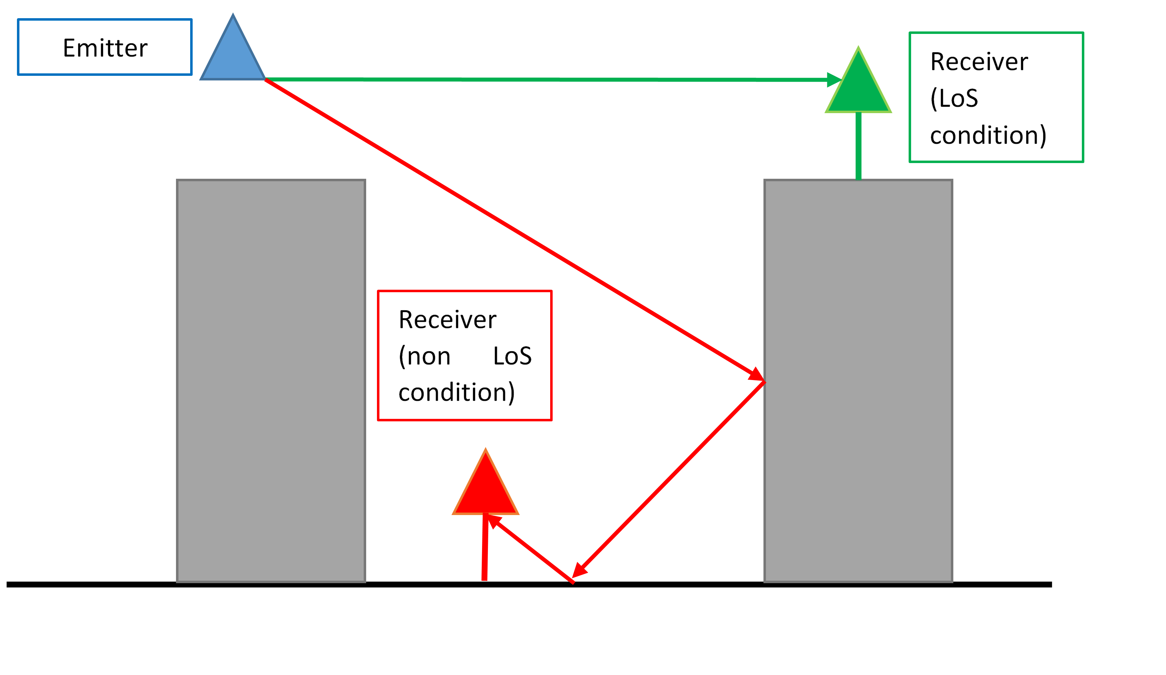
Scheme about the differences of line of sight and reflection condition
• Then, as the targeted satellite is moving around the Earth, the distance with our receiver is varying. Indeed, the satellite is farther when the elevation angle is low and the minimum distance is reached when it is at the zenith. The satellite is four times closer to the APT receiver at the zenith than on the horizon. It results in a loss of 12dB for low elevation angles. That’s why we need a larger gain on the horizon than overhead. This condition can be illustrated by the following chart.
Variation of the attenuation in function of the elevation angle of the NOAA satellite
As the properties needed are completely defined for the radiation pattern, we can detail and compare three possible RHCP omnidirectional antennas which are often used for APT signal and can accomplish adequate reception with a well-designed receiver:
• Turnstile antenna
• Quadrifilar helix antenna
• Double cross antenna
We will list the strengths and weaknesses of each and choose the best one for our case at the end.
Quadrifilar helix antenna
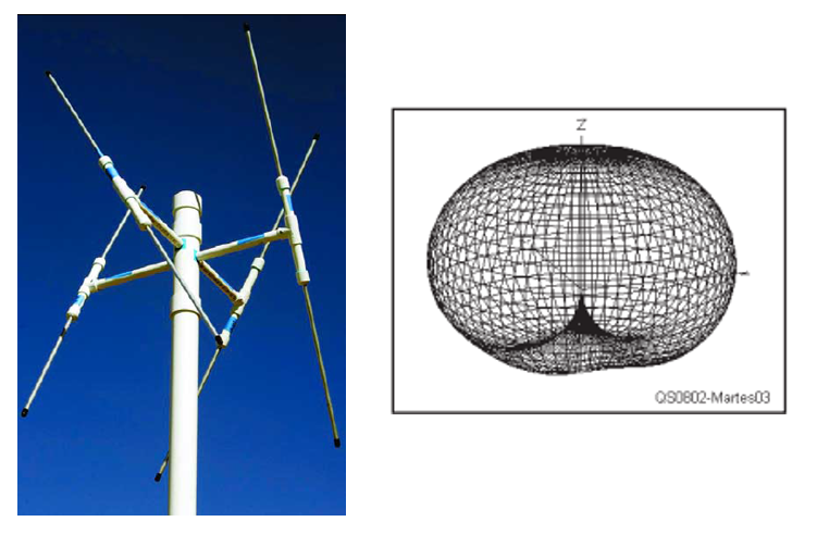
It consists of four half turn helices equally spaced around a cylinder. The helices length is defined according to the frequency. This antenna provides the most omnidirectional radiation pattern.

Quadrifilar helix antenna and its radiated pattern
It appears as the ideal pattern for receiving signals from polar orbiting weather satellites as the gain is almost the same in every direction. However, as we have seen before, we will use this antenna in a line of sight condition. So, the gain at the bottom of radiation pattern is useless. Moreover, due to the shape of the antenna, it is complex and costly to build. Consequently, this system would be expensive and oversized for our needs.
Turnstile antenna
It is built by placing two dipoles at right angles, each one with a size of half a wave length. In order to increase the gain, we usually stack two pairs of such dipoles. Designing such an antenna is simple and it is usually much less expensive to purchase than the quadrifilar one.
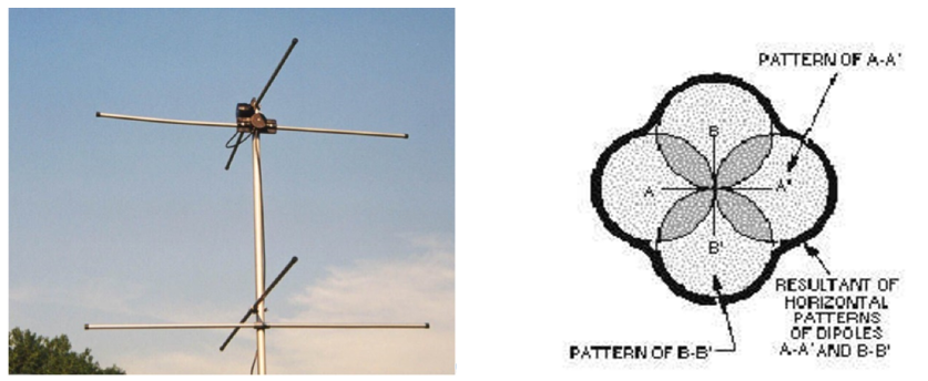
Turnstile antenna and its radiated pattern
The radiation pattern shows that in some directions at low elevation, the gain is reduced. It will provide slightly less performance because the satellite signal will be received at lower power in some direction than others. It results on some loss in the APT signal.
Double cross antenna
Four dipoles distributed in two pairs. Each dipole within one pair is spaced a quarter wavelength from the other one and the two pairs are crossed. In addition, each dipole is offset 30° to the azimuth.Thanks to this architecture, it is quite simple to build and much less complex than the quadrifilar helix antenna. This design gives such a radiation pattern:
Double Cross antenna and its radiated pattern
We can see that the gain at low elevation angle is larger than at the azimuth position and almost equal in every direction. Furthermore, the gain at the bottom is reduced so that is fits the line of sight condition which is required. In addition, it is cheap and easy to build.
Choice
We have seen so far, that the quadrifilar helix antenna has the most omnidirectional pattern but it is oversized for our needs and it is complex and costly to build. The turnstile is simpler and cheaper to make but its pattern does not respect our requirements. Finally, the double cross antenna fulfils every criterion and has a small price and low complexity to build. We will now detail the design.
Previous : System and signal description Next : Receiving antenna design
