
Build a receiving antenna » History » Version 10
« Previous -
Version 10/11
(diff) -
Next » -
Current version
AGUT SANZ, Sergio, 03/24/2015 12:02 AM
7. Build a receiving antenna
The next part was the construction of the antenna. It was based on the design of the Double Cross Antenna and the complete list of materials described previously.
Once all the materials had been cut to size and checked, the construction started with the four branches which contains the dipole. Each branch is composed of two 14 cm long PVC tubes, a PVC T fitting, an isolated board for the connections, a PVC end cap, two aluminium rods 51cm long and a coaxial cable whose length depends on the branch. The first step was to make one 2mm hole at the bottom of each dipole with the purpose of connecting the core or shield of the coaxial cable. We used an isolated board to ensure a better connection. As seen in figure 7.1, the two rods were fixed with cable ties to the board and we proceeded to connect each part. One rod connects to the core while the other rod connects to the shield of the coaxial cable. As a last step, we added the 2 PVC tubes and the two end caps fitted to the rods and secured them using glue for PVC. This same process was done to the other three branches. In order to identify the correct branch, each was marked depending on the dimension of the coaxial cable, with N, S, W or E (North-South measure 0,459m ; East-West measure 0.919m). Also the rod connected to the coaxial cable core was marked with a plus sign to help construction.
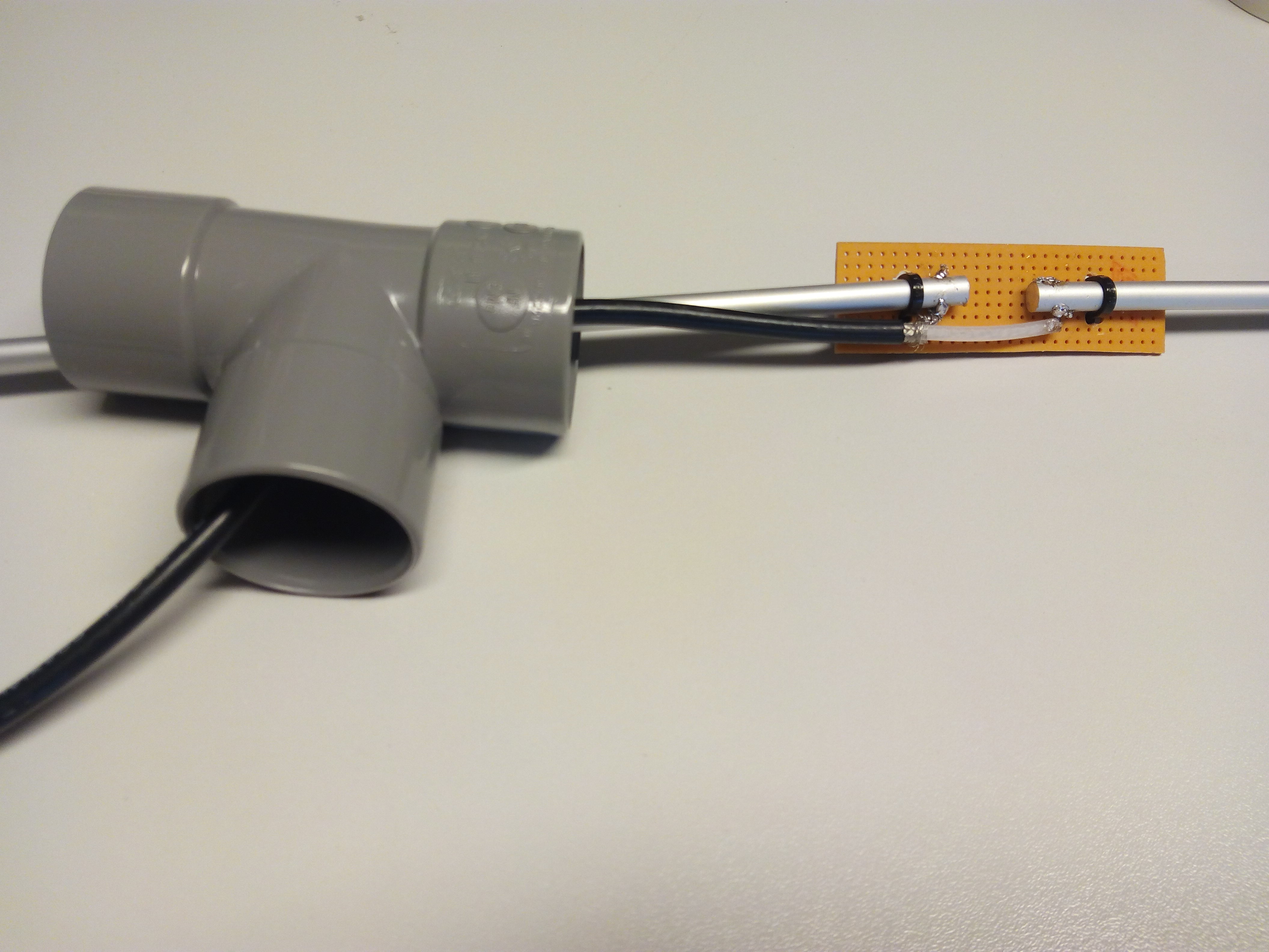
Figure 7.1: Connections in the PVC T

Figure 7.2: The PVC T once built
When this was finished, the central box of our antenna was built. The box is composed of a 15 cm long, 100mm diameter PVC tube, and a bottom and top cap to avoid the potential damage of the connection board. The first step was to make the four 32 mm diameter holes in the 100mm pipe and each 22mm PVC tube was fixed onto the box. In order to assure the fastening, brackets were used between both elements. The next step was to insert the coaxial cable of each branch in its correct position as is described above in the design part. Therefore, the North branch is situated opposite the South branch and the same for the East-West branches. After having assured the correct situation of each branch, each branch was connected with the end coaxial cable which will be used to connect the antenna to the receptor. The schema of the connections is shown in figure 7.3 .
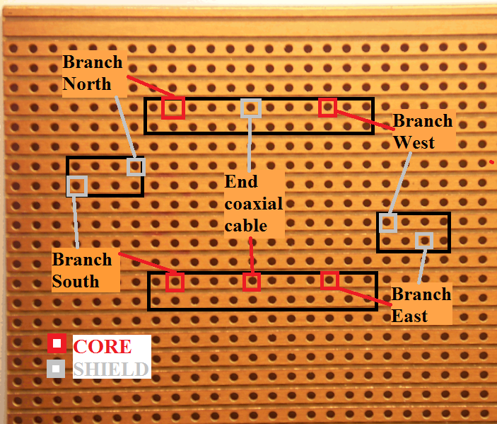
Figure 7.3: Connections in the central box between the four branches and the end coax cable
The end coaxial cable has a length of 3.5m to provide the connection to the output of the antenna using a female connector PL 259.
Once the connections were finished in the central box, the assembly of the four branches with brackets being careful with the coaxial cables. Lastly, we assembled the central box with the 50mm diameter PVC tube and length 1.5m with the aim of raising our receiving antenna. The Double Cross Antenna is ready to receive images since NOAA satellites. The DCA built at the Satcom lab can be seen in the next figure.
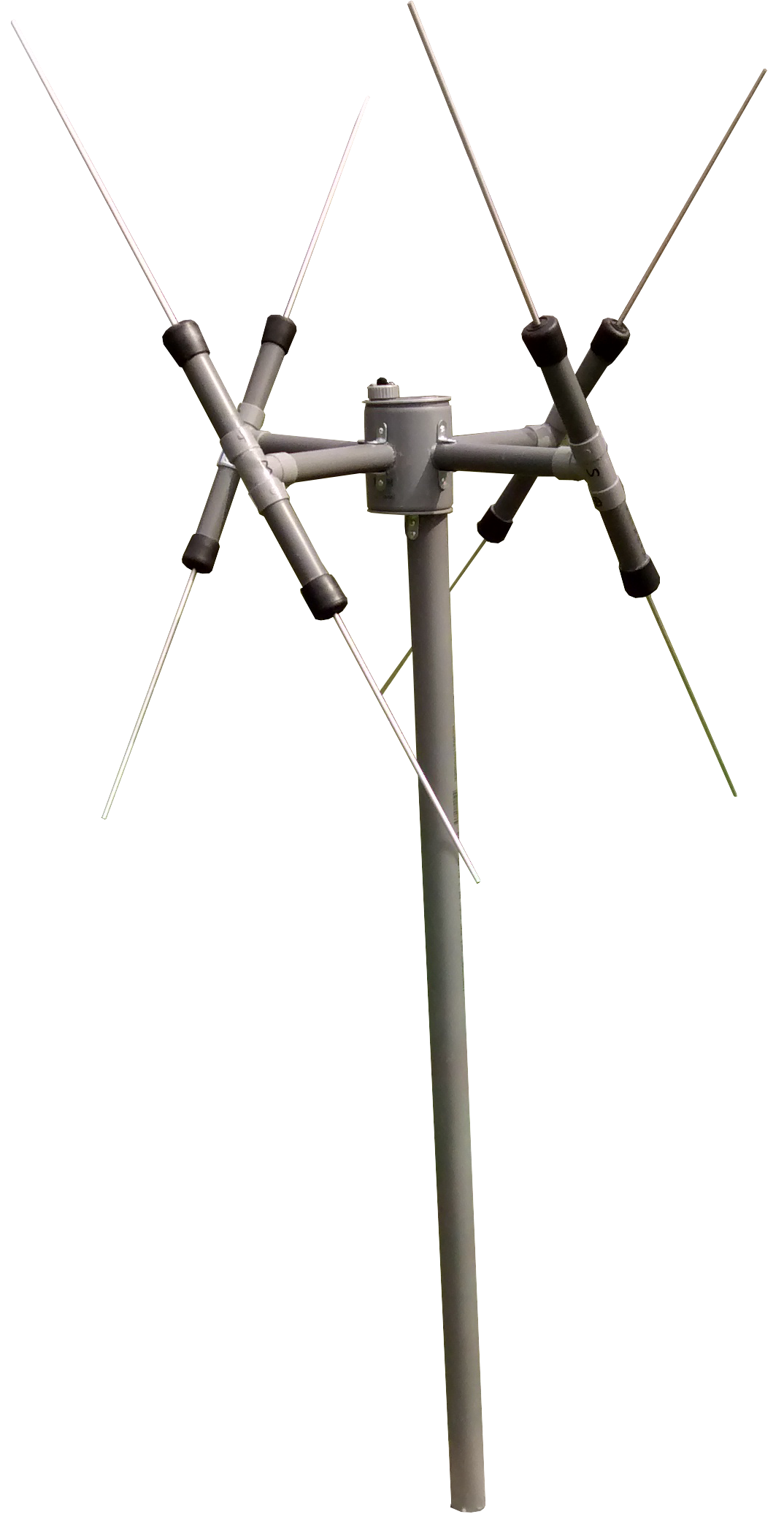
Figure 7.6: The DCA once built