
Receiving antenna » History » Version 34
« Previous -
Version 34/35
(diff) -
Next » -
Current version
AGUT SANZ, Sergio, 03/23/2015 11:20 PM
6. Receiving antenna
In this second part of the project, a receiving antenna will be built to collect the data information from the polar orbit weather satellites. The two main characteristics to have a great design are the polarization and the frequency used in the transmitting antenna. As it has been mentioned previously, the POES satellites transmit a signal with right hand circular polarization(RHCP), therefore the receiving antenna must be able to get the data at RHCP. From picture 6.1, it can be distinguished the both different components, one coming from the horizontal plane and the other, which is shifted 90 degrees, from vertical plane. Both components joinly create the RHCP. On the other hand, the frequency parameter is going to define the antenna size. Therefore, the first step will be to choose a specific POES satellite.
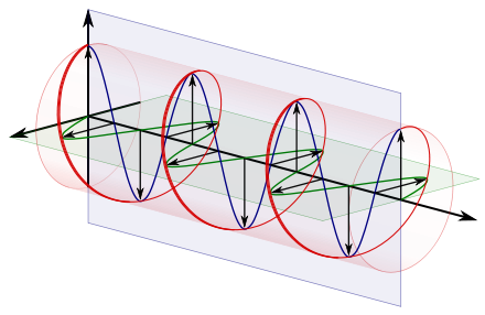
Figure 6.1: Right Hand Circular Polarization [1]
In the previous section has been explained the different transmission modes. In this project will be used the APT format, which sends the digital transmission in lower flowing traffic with respect to the HRPT mode. The APT mode sends the desired information at the frequencies from 137.1 MHz up to 137.9125 MHZ depending on the satellite. Currently, the available APT satellites are the following: NOAA 15 (137.62 MHZ), NOAA 18 (137.9125 MHz) and NOAA 19 (137.1 MHz). The chosen satellite is the NOAA 19 with frequency at 137.1 MHZ.
Therefore, for the reception of polar orbit satellites will be desirable to have an antenna which the following characteristics:
- Exhibits a radiation pattern in the upper hemisphere.
- It is sensitive in all directions only to right-hand polarised EM waves.
- It receives the information at 137.1 MHz.
In order to get the best choice, a study with three possible antennas have been done. It compares the advantages and drawbacks of each one. Finally, one antenna will be chosen and built. As a tool for the analysis has been used the SWOT, which allows to easily visualize the pros and cons of each option.
6.1 Study of the three possible antennas
6.1.1 TURNSTILE ANTENNA
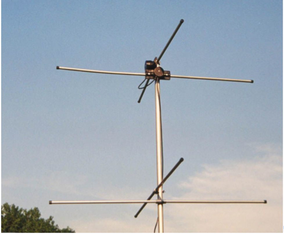
Figure 6.1.1.1: Turnstile antenna [3]
Turnstile antenna, also called Crossed dipoles, was created in 1935 by the American engineer George Brown. Turnstile is an omnidirectional antenna that can be used in horizontal, vertical and circular polarization; the latter polarization is used for satellite communications. [2] The antenna consists of the combination of two pairs of dipoles aligned and positioned at right angles to each other in the same horizontal plane. Each pair of dipoles is called a bay. [2] In addition, a current with the same magnitude and in phase quadrature feeds the antenna.
The phase quadrature can be done by feed-line techniques or by redefining the size of the dipoles. The most common feed-line technique consist in divide the signal using a two-way splitter and after, one of these two divided signals is progressive phase shifted 90°. On the other hand, changing the dimension of the dipoles and adding reactances in serial to them can modify the phase quadrature.
The antenna is built by combining two bays from ½ wavelength to each other and they are excited in phase to modify their radiation pattern. It is illustrated in the picture below.
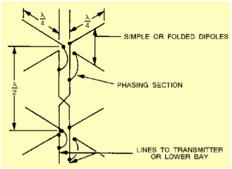
Figure 6.1.1.2: Turnstile antenna structure [2]
The vertical radiation pattern is modified because part of it is cancel by the vertical radiation generated by the other bay. It produces a decrease in the vertical radiation energy, but it increases the horizontal one while the vertical angles are also enhance. The Turnstile antenna radiation pattern is shown in the picture below. The image A shows the omnidirectional radiation pattern of a pair-bay. The image B presents the difference between a circular radiation pattern from a pair-bay and a four-bay. Finally, the image C illustrates the final radiation pattern of the Turnstile antenna.[2]
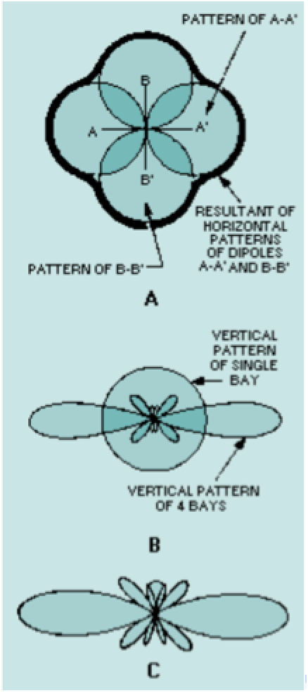
Figure 6.1.1.3: Radiation patterns of a Turnstile antenna [2]
There are two modes: Normal mode and axial mode. The normal mode radiates in horizontal polarization due to the position of the orthogonal pairs of dipoles that are in parallel between them and the floor. On the other hand, the axial mode uses circular polarization because the set of dipoles is perpendicular oriented to the receiver signal, in our case, it would be the signal transmitted by the NOAA satellite. Often, this mode is the selected one to satellite communication because by using circular polarization the polarization of the signal does not change with the movement of the satellite in its trajectory. [1]
6.1.2 QUADRAFILAR HELIX
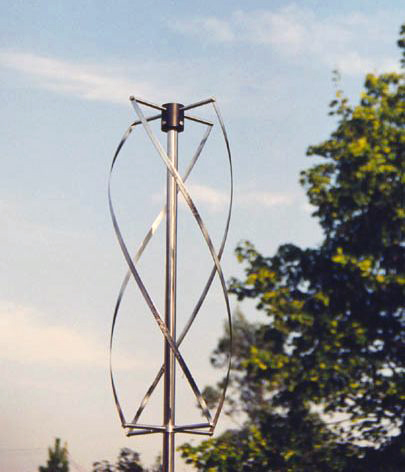
Figure 6.1.2.1: Quadrifilar helix antenna [4]
The second chosen antenna is the Quadrifilar Helix antenna, which is considered with a better performance compare to the previous one. It has composed of two sets of loops, which provides a better performance by reducing the noise and the eliminating null spots. The two loops with different sizes are called large loop and small loop. The terminals of each loop are fed 180° out of phase, and the current in the two loops are in phase quadrature (90° out of phase). [5]
By selecting the appropriate configuration of the loops, a wide shape of the radiation pattern is obtained. It also has an excellent axial ratio appearing over a large volume of the pattern. Therefore, the radiation pattern has a better performance than the previous antenna. From the figure 6.1.2.2, it can be seen a better signal reception due to most of the energy is received by the satellite from the horizon. Another advantage will be the possibility of using it in low heights. The drawback of this antenna is the complexity and implementation with respect to the other two.
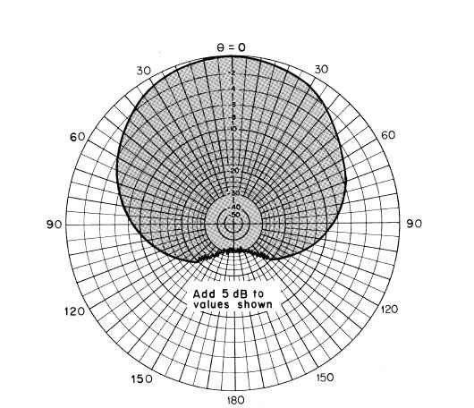
Figure 6.1.2.2: Radiation patterns of a quadrifilar helix antenna
6.1.3 DOUBLE CROSS
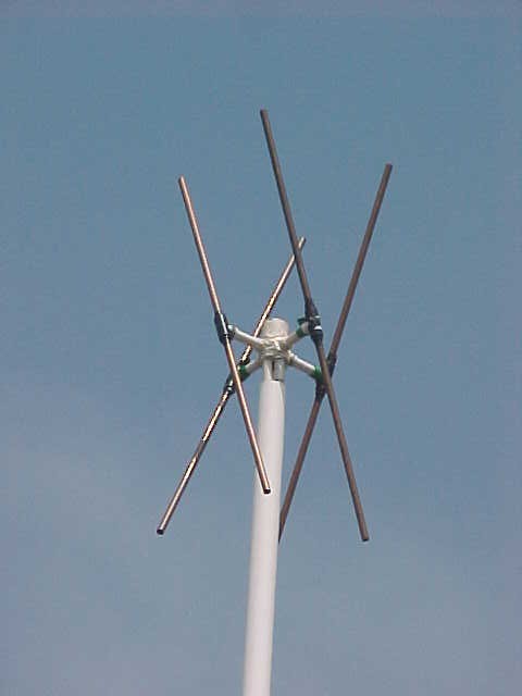
Figure 6.1.3.1: Double cross antenna [7]
Lastly, the third option is the Double Cross antenna (DCA). It is composed by two pairs of crossed dipoles (see figure 6.1.3.1). It also improves the performance of the radiation pattern with respect to the Turnstile antenna.
The purpose of the four dipoles is to produce a radiation pattern with great RHCP reception at the zenith axis. In order to achieve this pattern, the two dipoles have to be crossed, spaced a quarter wavelength and fed in phase. With this pair of dipoles is acquired a radiation pattern such as the figure 6.1.3.2.
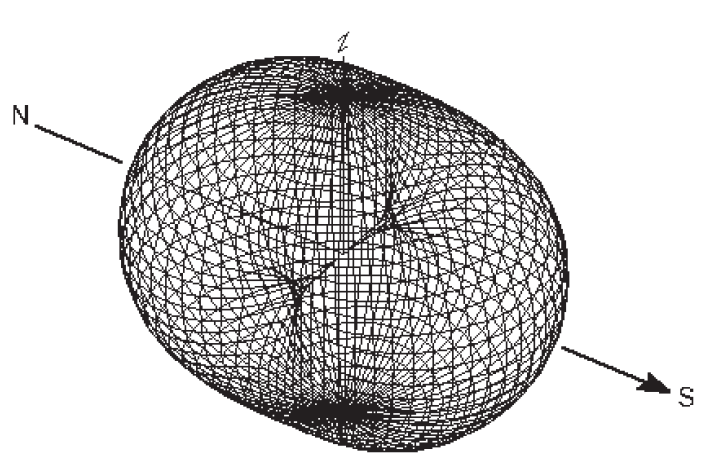
Figure 6.1.3.2: Radiation patterns of a pair of dipoles crossed, spaced a quarter wave and fed in phase [6]
As it can be seen, the X axis has a pattern null. Thus, it can be filled by adding a second pair of crossed dipoles but this last one should be fed 90 degrees later than the first pair. This phase shift can make by adding a quarter wavelength in a coaxial cable. Once the two pairs of dipoles are correctly establish, the final radiation pattern can be seen in the figure 3.1.3.3 .
Therefore, the DCA provides a high gain both upper angles and for the horizon angles. That increases the performance of the antenna. Furthermore, it has nulls for loud angles. This characteristic is very important because for the low frequencies, which are used by APT mode, are also used in terrestrial communications.
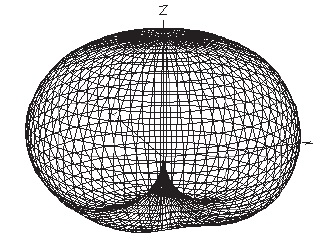
Figure 6.1.3.3: Radiation patterns of a double cross antenna [6]
REFERENCES:
[1] http://en.wikipedia.org/wiki/Turnstile_antenna#Satellite_and_Missile.2FRocket_Antenna
[2] http://www.tpub.com/neets/book10/42o.htm
[3] http://www.astrosurf.com/luxorion/qsl-satellites-reception.htm
[4] http://www.dartmouth.tv/marine/products_apt.htm
[5] http://www.jpier.org/PIERC/pierc39/10.13022105.pdf