6.3 Choice and design
Among all the antennas studied, double cross antenna has been selected to be built and used in receiving weather images, as previously mentioned, which are transmitted from POES NOAA satellite.
The most important reasons for selection were the following characteristics:
- Right Hand Circular Polarization (RHCP)
- Omnidirectional radiation pattern without many side lobes
- Does not need a rotor
- High efficiency in terms of low angles w.r.t. the horizontal plane
- High gain
- High level of robustness because this antenna works well even when the measurements of its design or frequency vary a little bit
- Medium level in terms of complexity of construction and price.
Moreover, the antenna will be fixed in the roof to facilitate the line of sight with the satellite. The received signal from the satellite is about twenty times higher in the zenith than in the skyline, therefore; it is necessary to have higher levels of gain in the lower angles corresponding to the position of the satellite around the skyline.
To accomplish this, the antenna is built according with the following schematic:
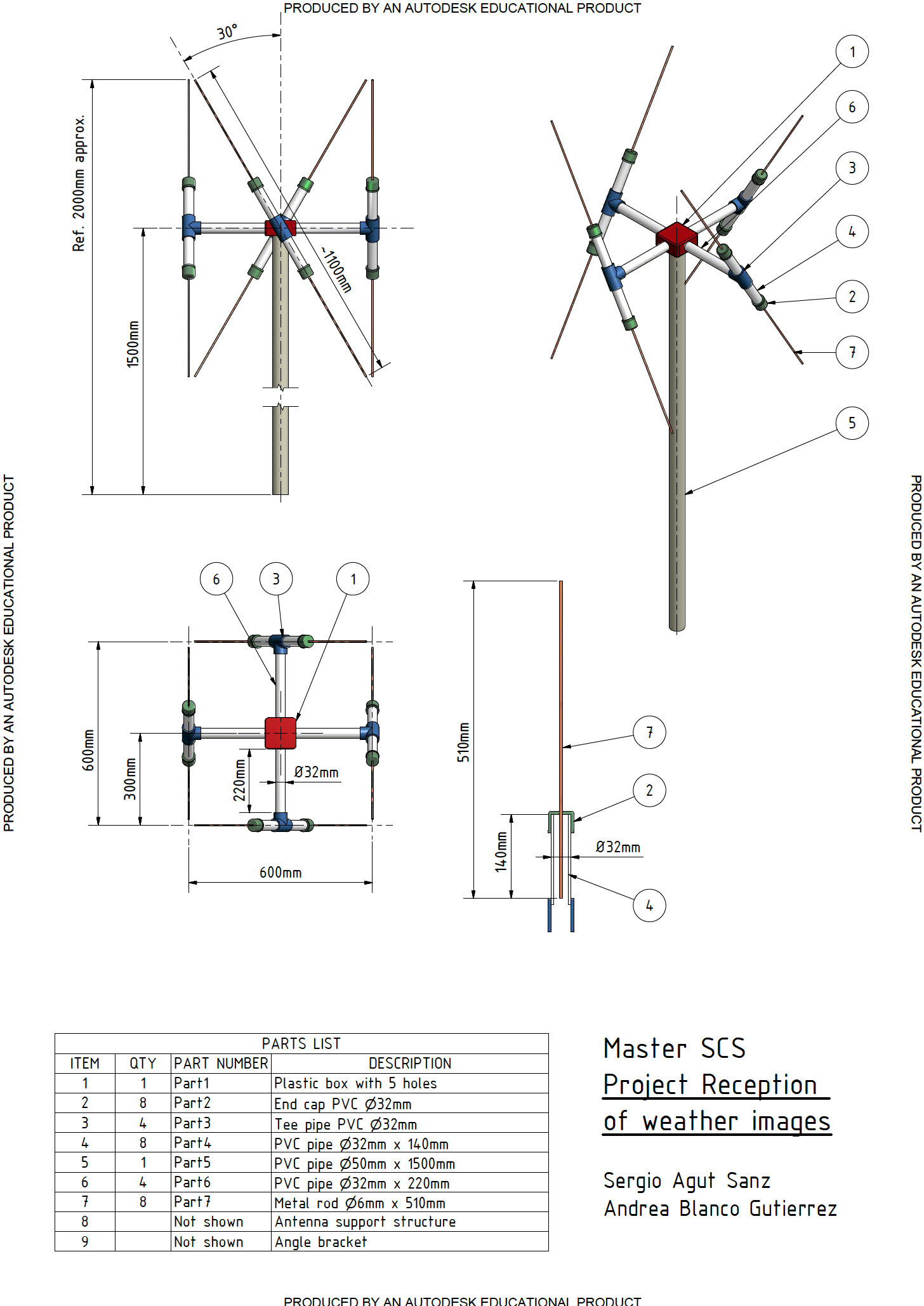
Figure 6.3.1: Double cross antenna AutoCad schematic
As it can be seen, the antenna consists in four equidistant dipoles spaced a quarter wavelength and each dipole is offset 30° to the azimuth. The dipoles are distributed in two pairs and within the pair the dipoles are crossed. The pairs are fed in phase, but one of the pairs is fed out of phase with respect to the other pair by 90°. In this project, the pair of dipoles North-South is 90° earlier than the pair West-East. The design of the antenna benefits the gain in the small angles, which correspond to the position of the satellite view on the horizon, in contradistinction to the gain acquired for the angles corresponding to the satellite seen on the zenith. The final radiation pattern of the antenna is isotropic as it has been explain in the previous section; hence, the antenna does not need a rotor.
In order to define the specific wavelength, which is the distance between two successive crests in a wave, will compute the required wavelength that is given by the next expression:
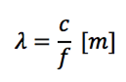 (6.3.1)
Where:
- c is the speed of the light, which value is
- f is the frequency.

The POES NOAA satellites use the range of frequencies between 137 to 138MHz. Concretely, it has been used in this project the frequency 137.1MHz due to it is the one employed in the satellite 19. Therefore, the wavelength is computed as following:
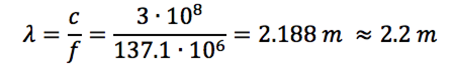 (6.3.2)
Then, the separation between dipoles is:
 (6.3.3)
Another important parameter to take into account is length of the coaxial cable in order to ensure the phase shift and a better coupling with the transmission line. This length should be chosen by the following expression:
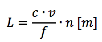 (6.3.4)
Where:
- L is the required length of the coaxial cable.
- ν is the velocity propagation factor of the coaxial cable, which is provided by the manufacturer in the data sheet. The coaxial cable RG58C/U, that has been used to build the antenna, has a ν equal to 0.84. [1]
- n is a constant parameter. It is necessary because of the length of the coaxial cable should be a multiple of half wavelength. In the project has been used the value of n equal to ¼.
 (6.3.5)
Therefore, the final length of the coaxial cable for each branch is define as following:

Figure 6.3.2: Comparative table: coaxial cable length
Another important consideration for the design is the connection of the dipoles. It should mounted as it is shown in the figure below:
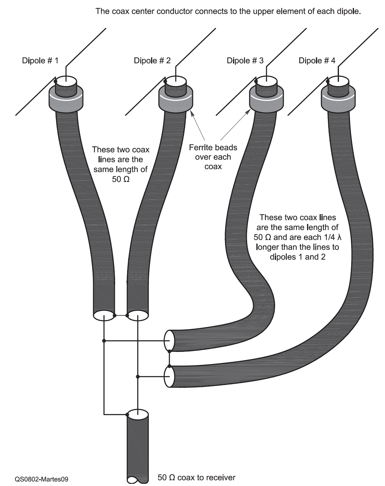
Figure 6.3.3: Connection design [2]
The meshes of the dipole 1 and 2 are connected together, in the same way that the meshes of the dipoles 3 and 4. The core of the dipole 1 is connected with the core of the dipole 3 to the mesh of the coaxial cable of the receiver. On the other hand, the cores of the dipoles 2 and 4 are connected with the core of coaxial cable of the receiver.
This connection assures the 50 Ohms impedance in the coaxial cable due to the impedance of the transmission line is the sum of the corresponding parallel coaxial cables of each dipole, which also results in 50 Ohm impedance. In addition, it is important to remark that the real implementation of this schematic has not take into account the ferrite devices.
References:
[1] Coaxial cable RG58C/U data sheet
[2] Double Cross — A NOAA Satellite Downlink Antenna
[3] Assembly Hints for Double Cross Antenna
[4] JM-137-DCA-KIT for NOAA POES APT
[5] GEO-DEC-2008-DCA
