Manchester decoding
This part seems to be critical for a lot of workers in the Manchester code. To decode the signal we have several approaches with different benefices for each one.
Some common steps are needed in all approaches;
• We should Know or discover the data rate clock
• We should synchronize to the clock to separate a bit edge from a mid-bit transition
• Process the incoming stream and recover the data using the previous two steps
• Store this data for further processing
All these steps should be implemented in software taking into account that we have 2 options based on timing and sampling.
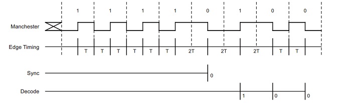
Timing based Manchester code
In this method, we detect the time between each transition coming from the demodulator circuit. To do this, we can use a micro-controller which contains an Input capture function. This function is used to deal with input signals in embedded systems (record time-stamp and set a flag indicating that an input has been captured). Moreover, it generates an interrupt, precise the time measurement and allow decision processing. To implement this method, we need the steps below;
1. Set up timer to interrupt on every edge
2. Interrupt service routine ISR should flag the edge occurred and store count value
3. Start timer, capture first edge and discard this.
4. Capture next edge and check if stored count value equal 2T (T = ½ data rate)
5. Repeat step 4 until count value = 2T (This is now synchronized with the data clock)
6. Read current logic level of the incoming pin and save as current bit value (1 or 0)
7. Capture next edge
a. Compare stored count value with T
b. If value = T
● Capture next edge and make sure this value also = T (else error)
● Next bit = current bit
● Return next bit
c. Else
if value = 2T
● Next bit = opposite of current bit
● Return next bit
d. Else
● Return error
8. Store next bit in buffer
9. If the desired number of bits is decoded; exit to continue further processing
10. Else set current bit to next bit and loop to step 7
It should also be noted that the timer’s value will not be exactly matched to T or 2T times.
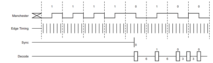
Sampling based Manchester code
In this method, we will sample and buffer the state at a certain rate (A), much higher than the message data rate. This needs more memory but allows less critical time to the processor to do intensive tasks.
Sampling is made by defining timer to interrupt and storing the state of the pin in a long buffer.
The software is implemented below
1. Set up timer to interrupt every 2T / S
2. ISR routine should check and store the state of the microcontroller pin (1 or 0)
3. Repeat step 2 for desired number of bits * S occurrences
4. Process through the captured buffer counting the number of consecutive ones or zeros
5. When the next logic value changes
a. Check if count >= (S/2); Then skip to step 6
b.Else reset count and loop to step 4
6. Set current bit = logic value in buffer currently pointed too
7. Reset count and count to the next logic change
a. Compare count with (S/2)
b. If count < (S/2)
● Reset and count to next logic change
● Make sure count also < (S/2)
● Next bit = current bit
● Store next bit in data buffer
a. Else if count >= (S/2)
● Next bit = opposite of current bit
● Store next bit in data buffer
a. Else
● Return error
8. Loop to step 7 until completely through captured data
9. Exit for further data processing
Conclusion
In this description, we show two approaches for Manchester code, each one has benefits and drawbacks. The user decide the most useful one for his application depending on the support functions provided by the microcontroller and degree of priority for the tasks in the system.
References
http://www.atmel.com/Images/Atmel-9164-Manchester-Coding-Basics_Application-Note.pdf
