EL470 Configuration
- Table of contents
- EL470 Configuration
IP Network Model
Modems will be interconnecting two IP network segments using IP bridging. This model is transparent meaning that hosts in the satellite subnet see the local and remote segments as being on same big subnet. However the HUB and Station modem know which IP range exists locally and which IP range exists at the remote site.
The Ethernet link is terminated by the modems in the same way that a router. Thus the Ethernet header and optional VLAN headers are not transmitted on the satellite link. This mode also has the advantage that ARP traffic and other L2 control messages are not sent over the link.
The satellite subnet is partitioned into distinct IP ranges so there will be a IP range for the HUB subnet and another for the Station subnet. In our case the satellite subnet is 10.0.0.0/24 and the HUB will serve 10.0.0/25 while the Station will serve 10.0.0.128/25.
In summary:
- The satellite subnet is divided into two subnets which are only visible to the modems.
- Only IP traffic with an destination address belonging to the remote site location will be sent through the link.
- Routers/hosts at both ends of the satellite link are "neighbouring routers/hosts" however the Ethernet link is terminated at the modem.

EL470 Configuration
Both HUB and station modems will be configured as L3 IP bridges. The following guide describes how to configure the direct link (HUB to Station) in ACM with a return link (Station to Hub) in CCM.
HUB Configuration
As an initial step, one can start by using the Setup Wizard configuration option on the management interface (accessed by a web browser on the management IP of the HUB modem). In this wizard we can input the following options:
- Network Topology: Point-to-Point
- Bridge Type: L3 IP Bridge
- Interface and Encapsulation Settings:
- Ethernet Port: A (needs to be consistent with wiring)
- Encapsulation: XPE
- CRC: Disabled
- Modulation Settings:
- Output Frequency: 1750 MHz
- Symbol Rate: 512 KBaud
- Roll Off Factor: 20%
- Output Level: -35.0 dBm
- FEC Frame Type: Normal
- ModCod: QPSK - 1/4 (Does not matter since we will be using ACM)
- Pilots Insertion: Disabled
- Demodulation Settings:
- Demod input: IFL 1 in
- Input Frequency: 1500 MHHz
- Symbol Rate: 512 KBaud
- Roll Off Factor: 20%
- Traffic Interface Settings
- Local LAN
- Device IP Address: 10.0.0.2
- Network Mask: 255.255.255.128
- Gateway Address: 0.0.0.0
- Remote LAN
- Network Address: 10.0.0.129
- Network Mask: 255.255.255.128
- Local LAN
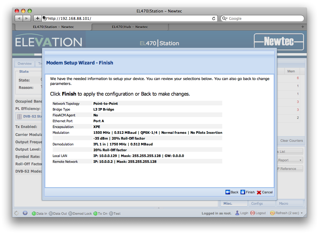
A summary of these options is shown before confirming:
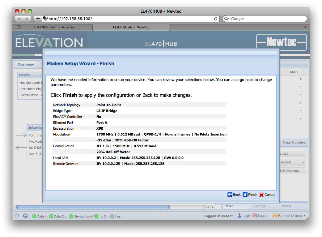
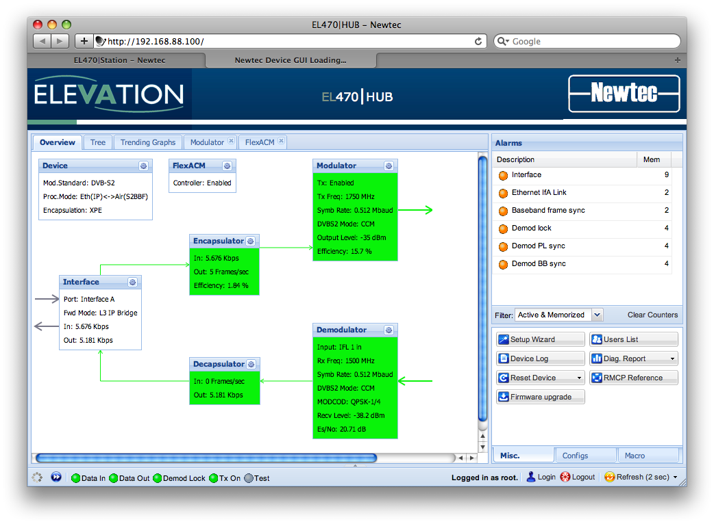
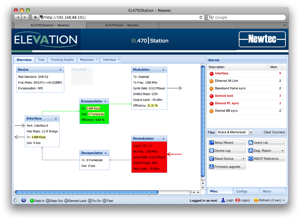
After confirming, the Overview tab in the management interface looks like this:
Notice that first of all, the modem is not transmitting (Modulator.TX = Disabled). Secondly, the demodulator is configured in ACM mode, we will take care of this by using the Tree tab and defining more specific options relating to the modulation and demodulation schemes. Note that only the following specified options have to be changed, the rest must remain with their default values which result from the setup wizard run.
General Settings
- Go to Tree >> EL470 >> Modem >> Control >> Common
- Set Processing Mode is to
Eth(IP)<->Air(S2BBF).
- Set Processing Mode is to
Modulator Settings:
- Go to Tree >> EL470 >> Modem >> Control >> Modulation >> Main
- Set DVB-S2 Mode to
ACM. - Set L-Band Transmit to
Enabled(This will enable the modulator output signal).
- Set DVB-S2 Mode to
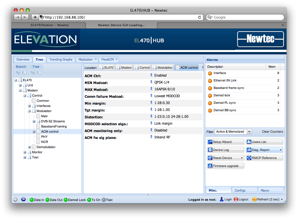
- Go to Tree >> EL470 >> Modem >> Control >> Modulation >> ACM Control
- Set ACM Ctrl to
Enabled. - Set MIN Modcod to the minimum MODCOD parameter desired in the forward link.
- Set MAX Modcod to the maximum MODCOD parameter desired in the forward link.
- Set Comm Failure Modcod to the default MODCOD parameter utilized if no ACM signalling is able to take place.
- Set Min Margin, Tgt margin, Distortion. For an explanation of FlexACM refer to FlexACM Functionality.
- Set MODCOD selection algo. to
Link margin. - Set ACM FW Sig Plane to
Inband RF.
- Set ACM Ctrl to
- Go to Tree >> EL470 >> Modem >> Control >> Modulation >> ACM Control >> Demod table
- Set the Demodulator IP of the first entry with the Virtual ACM client id IP address to be specified later on in the station parameters (we will be using 10.0.0.129).
Demodulator Settings:
Return link will always be CCM and we will use QPSK-1/4 with normal FEC-Frame types.
- Go to Tree >> EL470 >> Modem >> Control >> Demodulation
- Set DVB-S2 Mode to
CCM. - Set FEC-Rate and Mod to
QPSK-1/4 - Set FEC-Frame Type to
Normal
- Set DVB-S2 Mode to
Station Configuration
- Network Topology: Point-to-Point
- Bridge Type: L3 IP Bridge
- Interface and Encapsulation Settings:
- Ethernet Port: A (needs to be consistent with wiring)
- Encapsulation: XPE
- CRC: Disabled
- Modulation Settings:
- Output Frequency: 1500 MHz
- Symbol Rate: 512 KBaud
- Roll Off Factor: 20%
- Output Level: -35.0 dBm
- FEC Frame Type: Normal
- ModCod: QPSK - 1/4
- Pilots Insertion: Disabled
- Demodulation Settings:
- Demod input: IFL 1 in
- Input Frequency: 1750 MHHz
- Symbol Rate: 512 KBaud
- Roll Off Factor: 20%
- Traffic Interface Settings
- Local LAN
- Device IP Address: 10.0.0.129
- Network Mask: 255.255.255.128
- Gateway Address: 0.0.0.0
- Remote LAN
- Network Address: 10.0.0.2
- Network Mask: 255.255.255.128
- Local LAN
Summary of options looks like this:
And the Overview tab in the management interface looks like this:
As with the HUB, we must further define some other options:
General Settings
- Go to Tree >> EL470 >> Modem >> Control >> Common
- Set Processing Mode is to
Eth(IP)<->Air(S2BBF).
- Set Processing Mode is to
Modulator Settings:
- Go to Tree >> EL470 >> Modem >> Control >> Modulation >> Main
- Set DVB-S2 Mode to
CCM. - Set L-Band Transmit to
Enabled(This will enable the modulator output signal).
- Set DVB-S2 Mode to
- Go to Tree >> EL470 >> Modem >> Control >> Modulation >> DVB-S2 Streams >> DVB-S2 Streams
- Enable (Active field) the first stream entry and set FEC-Rate and Mod. and FEC-Frame Type according with whatever settings the HUB demodulator is using.
Demodulator Settings:
- Go to Tree >> EL470 >> Modem >> Control >> Demodulation
- Set DVB-S2 Mode to
ACM. - Set Max Achievable ModCod to preferred value.
- Set DVB-S2 Mode to
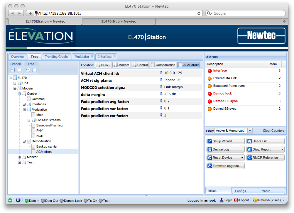
- Go to Tree >> EL470 >> Modem >> Control >> Demodulation >> ACM Client
- Set Virtual ACM Client ID to
10.0.0.129. - Set ACM RT Sig Plane to
Inband RF. - Set MODCOD Selection Algo. to
Link Margin - Set Delta Margin and Fade Prediction fields accordingly. For an explanation of FlexACM refer to FlexACM Functionality.
- Set Virtual ACM Client ID to
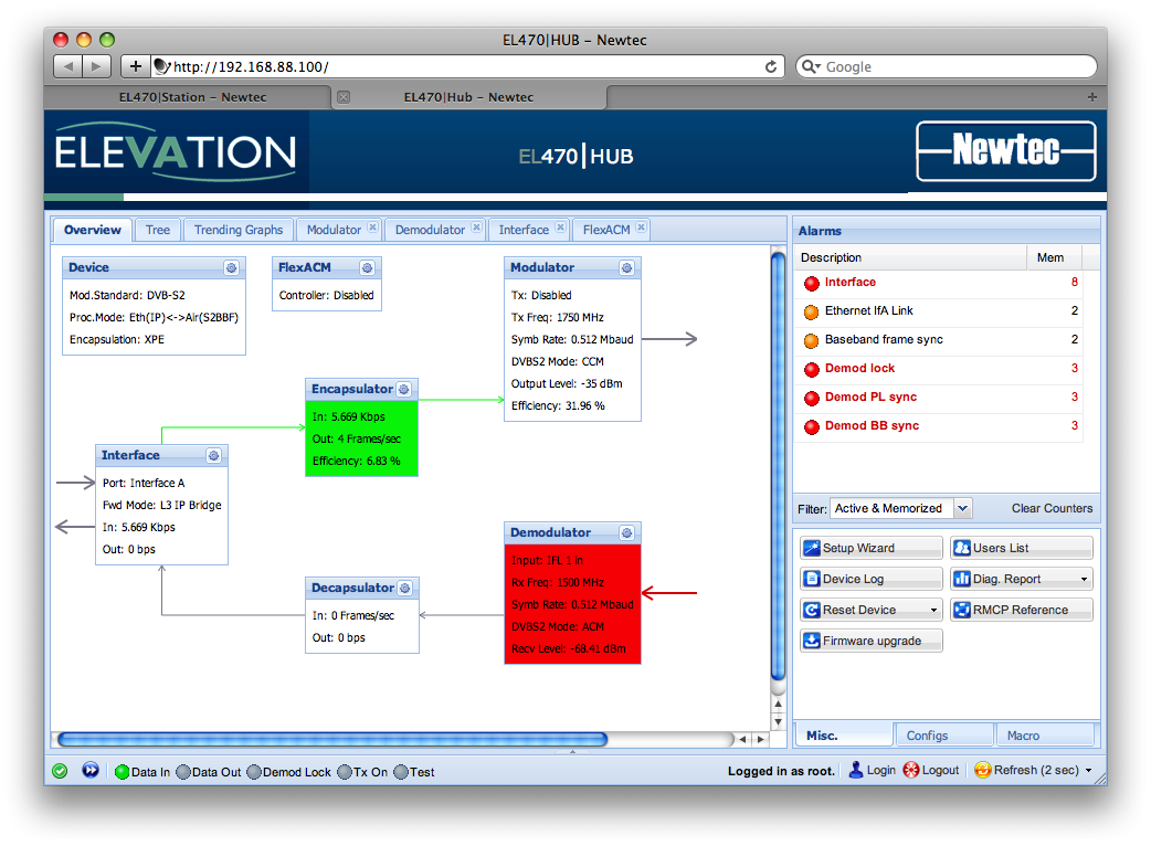
Established Links: Example
In the following screenshots we can see the management interface when a link has been established. Es/N0 estimates are of around 20dB and FW link is ACM while RT link is CCM with normal QPSK - 1/4 FEC-frames.
Station: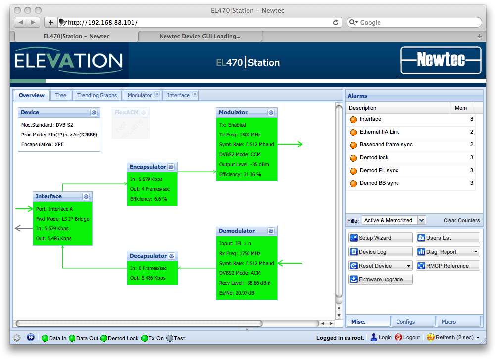
HUB: