Lab Setup
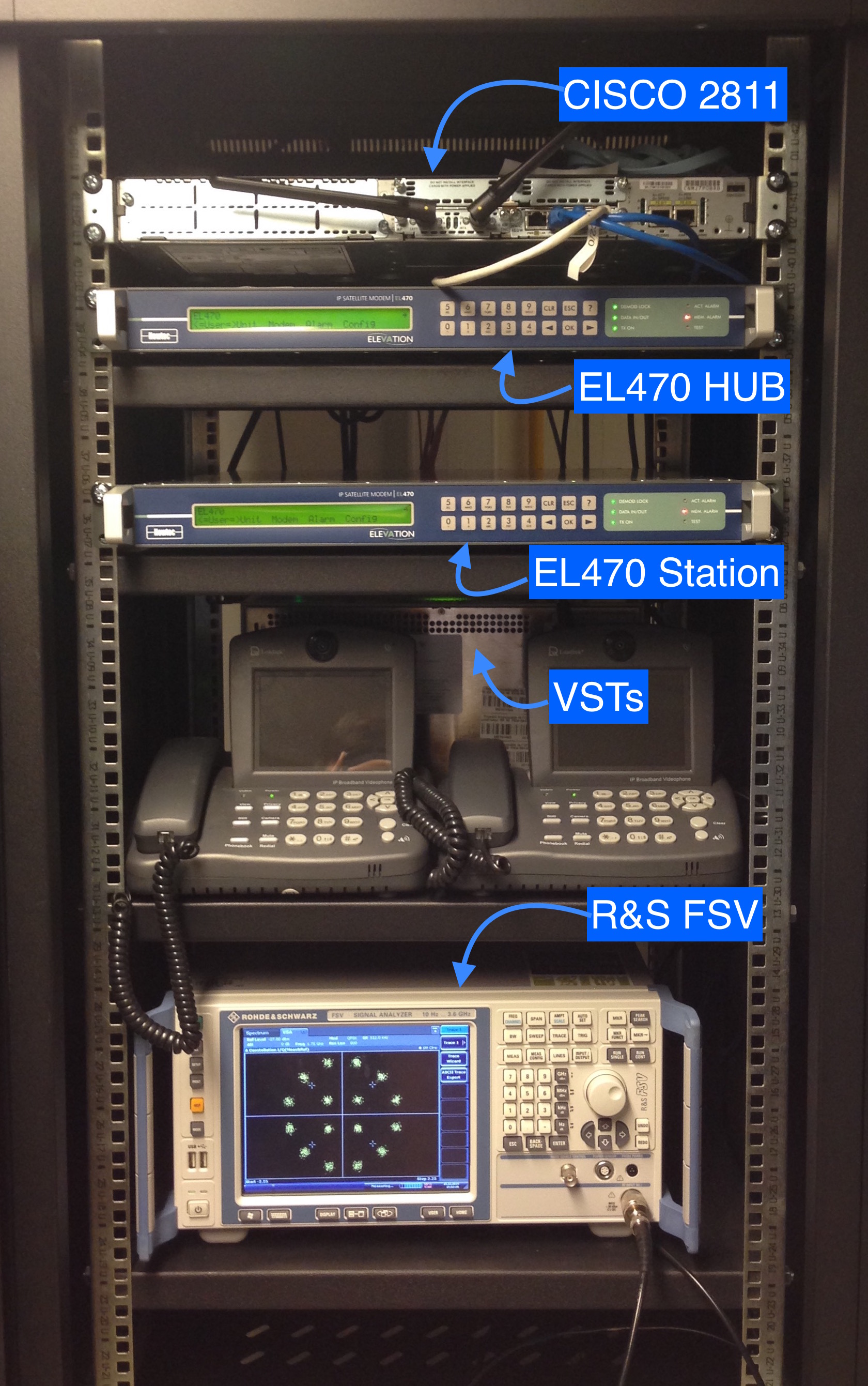
All measurements were performed in Telecom Bretagne's satellite communication labs in Toulouse. Our setup consisted of a main rack containing principal hardware and several control PCs. The first contains the DVB-S2 modems, a R&S signal analyzer, a networking switch and the link emulation hardware.:

Testbed rack.
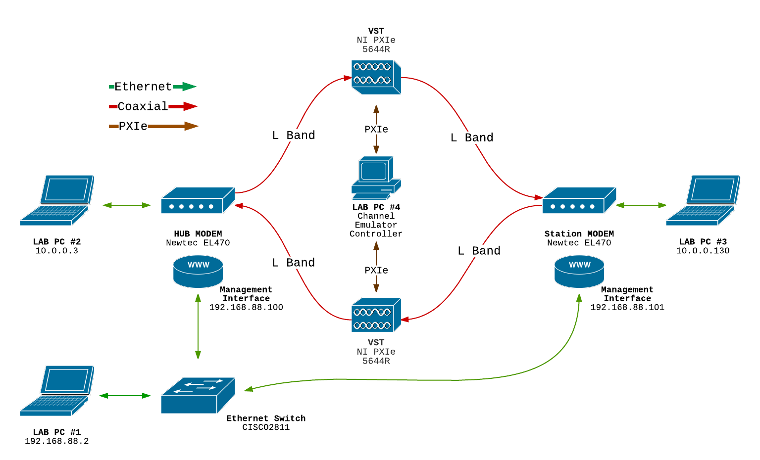
Connections as well as IP addresses are shown in the following diagram:

Measurement equipment:
1 x Rhode & Schwartz FSV Signal and Spectrum Analyzer

FSV showing 16APSK in action
Networking:
1 x CISCO 2811
1 x Newtec EL470 DVB-S2 HUB modem
1 x Newtec EL470 DVB-S2 Station modem
Link Emulation:
1 x NI PXIe-1078 Chassis
The NI PXIe-1078 nine-slot chassis features a backplane that incorporates a PCI Express connection to every slot to meet a wide range of test and measurement application needs. It accepts PXI Express modules in every slot and supports standard PXI hybrid-compatible modules. The chassis includes built-in timing and synchronization features including 10 and 100 MHz reference clocks as well as a PXI trigger bus.
2 x NI PXIe-5644R VSTs
The NI PXIe-5644R vector signal transceivers (VSTs) are part of a new class of instrumentation that combines a vector signal generator and vector signal analyzer with FPGA-based real-time signal processing and control. Because of this software-designed approach, a VST features the flexibility of a software defined radio architecture with RF instrument class performance.
1 x NI PXIe-8360 PXIe Controller
PCI Express card installed on laboratory PC to communicate with VSTs.
Lab PCs:
PC1 - Remote managing of Newtec modems.
PC2 - Data source for HUB modem, connects directly to HUB's ethernet interface A through a twisted pair cable.
PC3 - Data source for Station modem, connects directly to Stations's ethernet interface Aa twisted pair cable.
PC4 - Channel emulator controller, handles processing of VST acquired signals.
