Link Emulation
Telecom Bretagne has resorted to SDR based channel emulation. This approach is very attractive because of its low cost and flexibility. Typically hardware-based radio channel emulators are over 100k€ and seldom affordable for academic use.
The architecture is simple, instead of connecting both modems back to back, a VST is inserted in each link. A Vector Signal Transceiver (VST) combines a vector signal analyzer with a vector signal generator. This allows for real-time signal processing with which we will emulate channel conditions. For more information please refer to a paper published by our tutor Laurent Franck in which SDR based channel emulation is discussed: document:"COST EFFECTIVE EMULATION OF GEO SAT CHANNELS" .
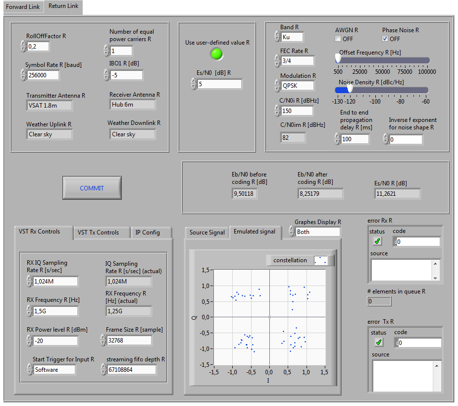
On the control PC (LAB PC #4) a custom software implemented in LabVIEW handles signal processing and seeks to set the Es/N0 for a particular link. The following are screenshots of the software front panel for both forward and return links:


The low part of the front panel contains the following sections:
- Error Tx
- Error Rx
- Signal display
- VST Rx Control
- VST Tx Control
- IP Config
The first two show errors such as buffer overflows and such, it is important to keep an eye on this since it maintains emulation accuracy. We should not have any messages here. The signal display simply shows the quadrature and in-phase components of both the input and output signals of the VST. The IP Config tab is important in order to determine which VST device is associated with a given link.
The rest of the front panel contains buttons and checkboxes pertaining to different parameters of the channel emulation.
notice. Be sure to set the frequency, RollOffFactor and Symbol Rate fields according to whatever settings are being used in the modems.
notice. Maximum IQ sampling rate tested was 2,048M.
A different variant of this software is available, instead of manually defining values, an input file containing a time series of Es/N0 values is loaded.
