
Concept
- Table of contents
- Concept
Cubesats
In 2003, the first Cubesats were launched to space. By 2014, more than two hundred of these satellites have been put in orbit, and the number continues to grow. They are extremely popular in the academic institutions and space organizations all over the world.
In 1999, Jordi Puig-Suari (from California Polytechnic State University) and Robert Twiggs (from Stanford University) developed the CubeSat standard to help universities and educational institutions worldwide access to space exploration and research activities. Designed to be compatible with the Poly-Picosatellite Orbital Deployer (P-POD), their size is measured in unit sizes (1U = 10 cm x 10 cm x 10 cm). The most popular platforms are of 1U, 2U and 3U. Their mass goes from 1kg (for the 1U) up to 4kg (for the 3U), putting them in the classification of nanosatellites or picosatellites. Thanks to their dimensions and mass, they are easy to send to space at lower costs, since they are usually piggybacked with other, larger, missions.

Different sizes of cubesats.
Despite their small size and weight, they can be used to test a wide variety of devices in space environment, from simple cameras to multi-spectral cameras, used in complex studies of the ionosphere; and also to perform more complex experiments and measurements in the domains of Astronomy, Biology, Atmospheric sciences, Earth observations, etc. [1]


On the left, Pharmasat with dishes for growing yeast in space. On the right, DICE cubesat, with probes for measuring electron density.
Cubesats are usually placed in low Earth orbits (LEO), defined as 160-2000 km above the Earth’s surface. Many of them, are stationed between 600 and 800km of altitude, below the Van Allen belts, and safe from most of the radiation present in space. This makes it possible to use commercial-off-the-shelf electronics, not suitable for harsher environments, where the Sun’s radiation is an issue.
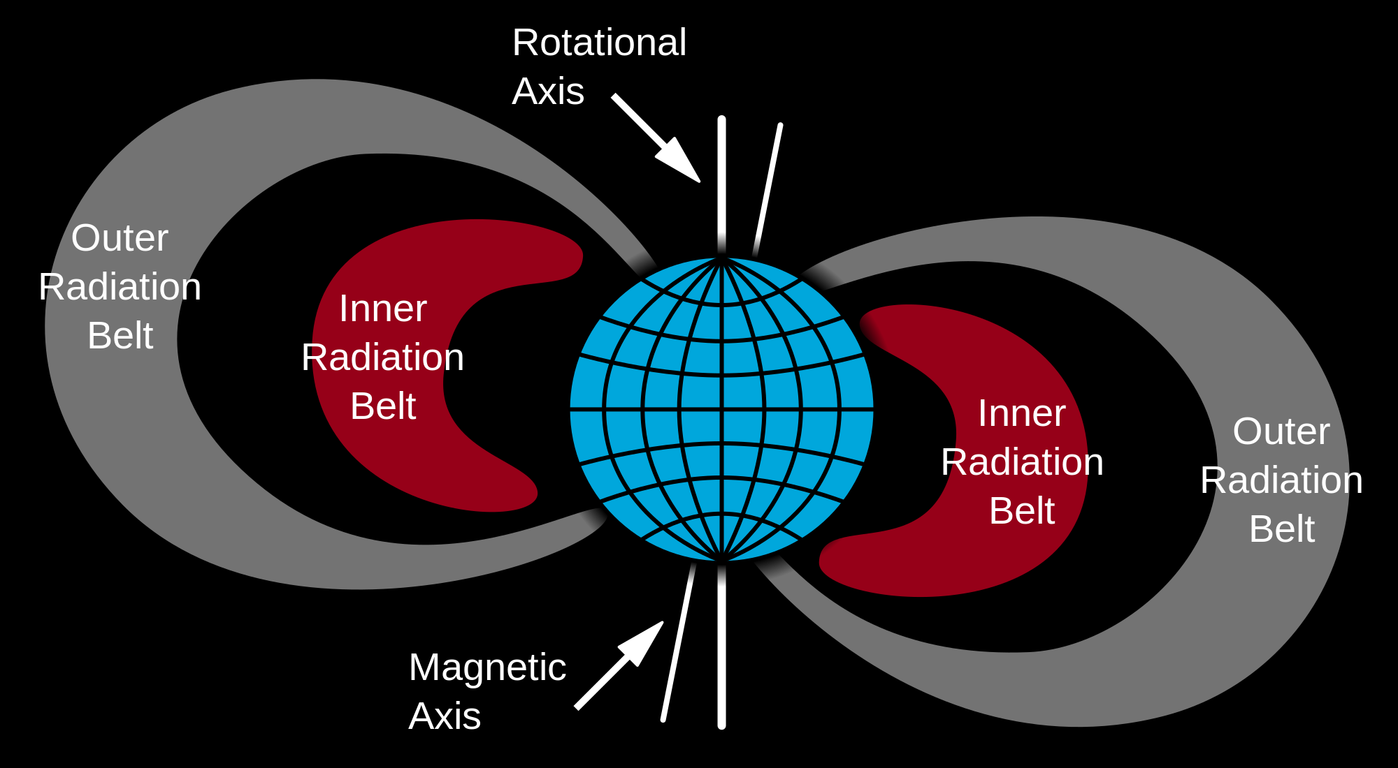
Inner belt extends approximately from 1000 km to 6000 km of attitude.
The lower price of off-the-self electronics, together with the lower launching price with make their cost considerable lower than other types of satellites, and affordable to educational institutions. A wide variety of ready-to-use CubeSat kits compliant with the standard are available on the market, saving the effort of building its own hardware and allowing to quickly experiment with this kind of platform.
In order to be compatible with the launchers, and respect the normatives, the Cubesats must meet some requirements defined in the standard [2]. Some of its key points are:
- Total stored chemical energy shall not exceed 100 Watt-Hours.
- Out-gassing materials must be NASA approved.
- Dimensions are specified by diagrams, and limit maximum dimensions, size of the rails, excess of components on the surface, etc.
- Single Cubesats shall not exceed 1.33kg mass; triple CubeSat, 4.0 kg mass.
- The CubeSat center of gravity shall be located within a sphere of 2cm from its geometric center.
- Aluminum 7075 or 6061 shall be used for both the main CubeSat structure and the rails. If other materials are used the developer shall submit a DAR and adhere to the waiver process.
- The CubeSat shall use separation springs, with characteristics defined on the standard.
- No electronics shall be active during launch to prevent any electrical or RF interference with the launch vehicle and primary payloads. CubeSats with batteries shall be fully deactivated during * launch or launch with discharged batteries.
- The CubeSat shall include a Remove Before Flight pin or launch with batteries fully discharged. the RBF pin shall be removed from the Cubesat after integration into the P-POD.
- For amateur frequency use, this requires proof of frequency coordination by the International Amateur Radio Union (IARU). Applications can be found at www.iaru.org.
- The orbital decay lifetime of the CubeSats shall be less than 25 years after end of mission life.
Overview of the RTTY telecommunication system
Before introducing the description of the satellite's payload and the complete communication chain, it is necessary a brief introduction of the RTTY system, which stands for Radioteletype. RTTY is a telecommunication system composed by two or more terminals linked by radio rather than wires. These terminals consist of two different parts: the teleprinter and the radio transceiver.
The teleprinter
At the beginning, RTTY teleprinters were electromechanical devices with the main task of translating the binary information transmitted through the link into an alphabet and vice versa.
Nowadays, the teleprinter is an electronic device which has one input and one output interface. Usually, the input interface is a keyboard and the output is a screen allowing the user to read the alphabet.
As it was implicitly introduced, the transmitted information is digital, which means that there are only 2 symbols: logic "0" and "1". When no traffic is passed, the link turns to the "idle" state, represented with a logic "1".
When a character is generated by a terminal, it is coded into a 5-bit word. Then, it is transmitted as a sequence (serial format) in the following way:- start bit (a logical "0" or space)
- 5 data bits
- stop bit (a logical "1" or mark, lasting 1, 1.5 or 2 bits)
At the receiver side, when a sequence matches the pattern previously presented, the 5 data bits are converted to a character of the alphabet.
The alphabet
The 5 data bits only allow to have 32 different codes, which cannot accommodate the size of a common alphabet with more than 20 letters, 10 numbers, space, punctuation characters and control codes, such as carriage return, new line, etc.
To overcome this limitation, it has been developed an alphabet based on two states. The first one is unshifted, and it holds the letters. The other one is the shifted state which holds the numbers and the punctuation marks. The change from one state to the other takes place when the special control codes "letters" and "figures" are sent from the keyboard or received from the line. This alphabet was developed by Émile Baudot in 1870 for telegraph communications and it is called Baudot code. Although it is well known all over the world, it is possible to work with other variations like adding another third shifted state which can hold more characters.
The Baudot code
The Baudot code is a character set which represents each character in the alphabet by a series of bits. The table presented below shows all the alphabet symbols and their 5-bit character representation.
| 5-Bit pattern (RLSB) | Character | |
|---|---|---|
| Letter shift | Figure shift | |
| 00000 | NULL | NULL |
| 00100 | Space | Space |
| 10111 | Q | 1 |
| 10011 | W | 2 |
| 00001 | E | 3 |
| 01010 | R | 4 |
| 10000 | T | 5 |
| 10101 | Y | 6 |
| 00111 | U | 7 |
| 00110 | I | 8 |
| 11000 | O | 9 |
| 10110 | P | 0 |
| 00011 | A | - |
| 00101 | S | BELL |
| 01001 | D | Who are you? |
| 01101 | F | ! |
| 11010 | G | & |
| 10100 | H | # |
| 01011 | J | ' |
| 01111 | K | ( |
| 10010 | L | ) |
| 10001 | Z | " |
| 11101 | X | / |
| 01110 | C | : |
| 11110 | V | ; |
| 11001 | B | ? |
| 01100 | N | , |
| 11100 | M | . |
| 01000 | Carriage return | Carriage return |
| 00010 | Line feed | Line feed |
| 11011 | Shift to figures | |
| 11111 | Shift to letters | |
The transceiver
The transceiver is the electronic device in charge of (for the emitter case) translating the logic levels into symbols, modulating them and generating the RF signals to be transmitted in pass band. In the opposite way, for the receiver case, it is in charge of receiving the RF signals, demodulating them and finally translating into logic levels.
The modulation consist in converting the digital signal into a pair of frequency tones. Depending on the type of modulation and the constellation there are several option. Traditionally, it is used a pair of tones within 2295/2125 Hz (for US) or 2125/1955 Hz (for Europe). Then, this tones feed the transmitter in order to generate the final AFSK signal which modulates an RF carrier. Also, it is possible to implement direct digital to FSK translation if the transceiver allows it.
At the receiver side, the FSK signal is converted to the original tones by mixing the FSK signal with a local oscillator. Thus, these tones are fed to the demodulator, which processes them through a series of filters and detectors to recreate the original digital signal, and translates the frequencies into logic levels: "0" and "1".
Typical modulation schemes used in RTTY systems are shown below:
- Modulation: FSK (F1B)
Type: Frequency modulation
Modulating signal: One channel containing digital information, no subcarrier
Application: Electronic telegraphy (radioteletype and digital modes)
SCHEME 1
- AFSK + VHF/UHF carrier (F2B)
Type: Frequency modulation
Modulating signal: One channel containing digital information, using a subcarrier
Application: Electronic telegraphy (radioteletype and digital modes)
SCHEME 2
- AFSK + VHF/UHF carrier (A2B)
Type: Double-sideband amplitude modulation
Modulating signal: One channel containing digital information, using a subcarrier
Application: Electronic telegraphy (radioteletype and digital modes)
SCHEME 3

Figure showing the typical modulation schemes used in RTTY chains
Typical transmission rates stand between 50 and 300 baud. Common carrier shifts are 85, 170, 425, 450 and 850 Hz, but normally there are some station using non-standard shifts.
References
[1] "Cubesats: Cost-effective science and technology platforms for emerging and developing nations", Woellert et al.
[2] "CubeSat Design Specification".
[3] "Wikipedia: Radioteletype".