
Further improvements » History » Version 32
« Previous -
Version 32/36
(diff) -
Next » -
Current version
SERRA FONT, Anna, 03/24/2015 01:38 AM
Further improvements
As we have seen, the link budget equations can become very complex and, during the two months we have had to develop this project, sometimes we have had to do some assumptions in order to simplify the calculus and thus achieve a coherent software tool.
At the beginning of the project we did a long list of all possible options and features that could be included in a link budget tool, selecting them by order of priority in order to implement them.
Finally, in this last part is shown a list of other features and improvements that could be performed for future students.
System Geometry
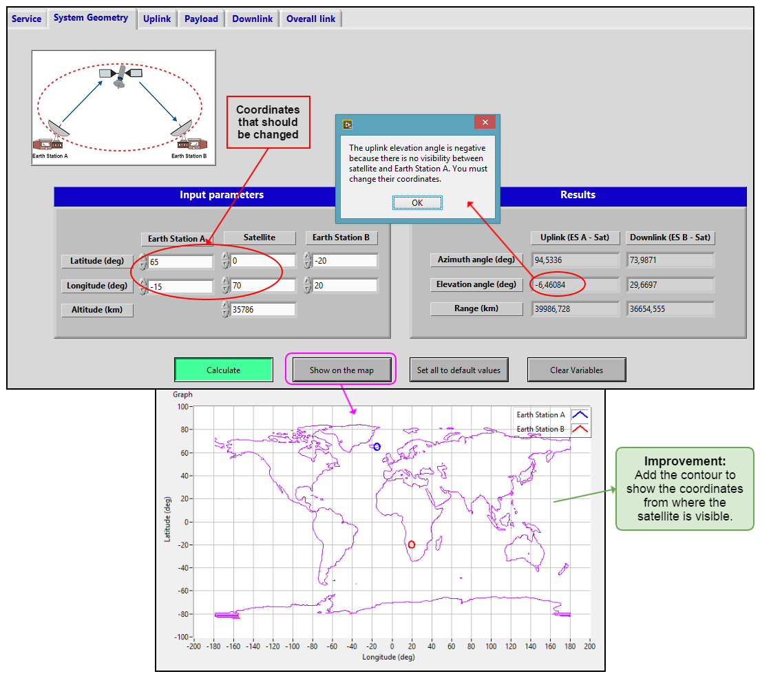
It can occurs that when the user calculates the elevation angles of the system, these give a negative value. It occurs when the earth station has no visibility with the satellite due to the latitude and longitude introduced.
Currently the SatLinkTool is designed so that a popup warning users appears when this happens. Pressing the 'Show on the map' button the user can see on the map where its earth stations are located, and a further improvement would be to add a contour with the satellite visibility, i.e. mark on the map all the coordinates from where earth stations have visibility to the satellite (and hence an elevation angle greater than 0) to facilitate the user the right choice of latitudes and longitudes.
SERVICE
Another possible improvement is to increase the possible values of $BER$, the corresponding $\frac{Eb}{No}$ and code gains. Currently, the possible values of modulation that are implemented are based in a table of the situation of Quasi-error-Free. This table is shown in the figure below, obtained from the "Satellite Communication System" book (page 156) [1]. Quasi-error-free (QEF) means that we will have less than one uncorrected error event per hour, for this table this situations correspond to a PER (Packet error ratio - relative to the symbols) about $10^{-7}$ .
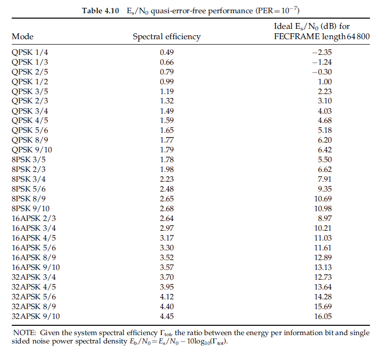
<div style="margin-left: auto; margin-right: auto; width: 30em">Figure 1 - Table applied in SatLinkTool, Quasi-error-free situation, from reference [1].
</div>
$$$$
We would like to add others situations, for instance the case without FEC, that is when code rate = 1. We had already started this implementation. In the first steps we have implemented (for QPSK, BPSK, 8PSK, 16PSK and 32PSK) the graphic of $BER$ vs $\frac{Eb}{No}$. One possible option would be to take the value of $\frac{Eb}{No}$ from a user input of $BER$, and then perform the calculations. This implementations in labview can be seen below.

<div style="margin-left: auto; margin-right: auto; width: 40em"> Figure 2 - Possible reference application to further increase of $BER$ possibilities </div>
Note: To take the $\frac{Eb}{No}$ value from a $BER$ input you can explore matlab functions like solve(x,y).
DOWNLINK
In downlink we have as an input the $Tsky$ which can be assimilated as the brightness temperature for a given antenna angle of elevation and a given downlink frequency. As we have done with the $ho$ value, which is take automatically by the input position of the earth stations, in further improvements we can also help the user and automated the process to take $Tsky$ values using the following graphics. Probably this graphics can be obtained in ITU site [2] or EUTELSAT site [3] in versions which we can manipulate with MATLAB. Then, the tool can be programmed to take directly the input values, hence the user will have an approximation nearer to the real implementation. In figure 4 it can be seen the graphics that can be used for the further improvements mentioned.
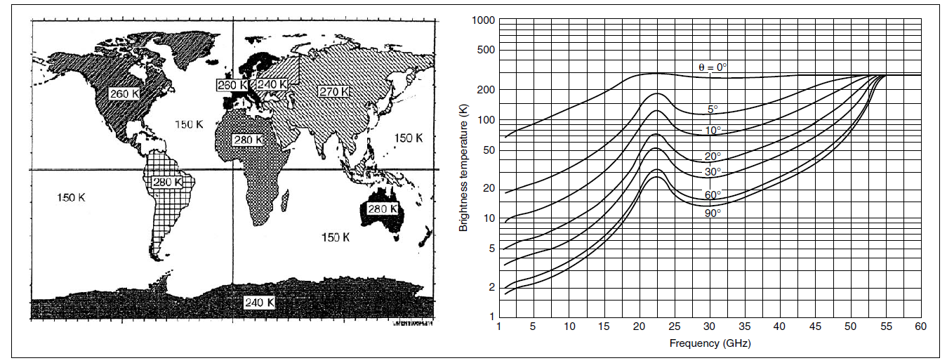
<div style="margin-left: auto; margin-right: auto; width: 70em"> Figure 3 - In the left side The ESA/EUTELSAT model of the earth’s brightness temperature at Ku band - From [FEN-95]., in the right side brightness temperature in function of frequency and elevation angle(7:5 g=cm3 humidity at ground level) - From CCIR Rep 720–2. </div>
PAYLOAD
We have developed the firsts steps to calculate the total depointing angle. They consist in the angles of satellite-earth station geometry angles ($\alpha $, $\alpha$*, $\beta$, $\beta$*) and the true view angles($\theta$, $\varphi$). In the matlab code applied in this step we also have more useful information like the distance of the satellite to the Earth location $R$ values. One further improvement is to finalize this implementation to perform the total depointing, and then the minimum antenna diameter of receiving Earth Station (ES B in Satlinktool). The pre-defined window for this implementation is the Depointing 2, located in Payload -> Antenna. This window is showed in figure 5, here below:
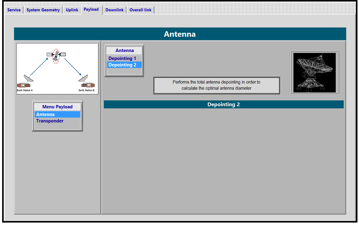
<div style="margin-left: auto; margin-right: auto; width: 40em"> Figure 5 - Pre-defined window to finalization of total depointing angle computing </div>
GENERAL IMPROVEMTES
We can summarize the general improvements (in addition as these mentioned before), in the following points:- Improve the apresentation of SatlinkTool: Lock tables, form groups, think about the presentation of each window, evaluate the relevance of each action executed and highlight the mean points.
- Improve the Payload : Think about the transparent Payload, put more options of multicarriers, establish a coherent relation with ${(C/N)}_T$, reevaluate the application of $IBO$, $OBO$ taking TWTA power models, consult teachers, books, sites, etc. Also think about the possibility of have the Regenerative Payload calculation option.
- Thinking about extend the application not only to the GEO satellites, but for more types.
- Take data from developed models of satellites and include it like an option of "default values", having the possibility to check and perform their Link Budget.
- Thinking about the presentation of final results, if it's really clear, provide creative presentations, see what can be kept and what can be change.
- Apply a calculate button that perform and update all main calculations in each all tabs ( to avoid update the computing by press one by one calculate button in the windows). One possibility is use an interruption.
REFERENCES
[1] Maral, Gérald / Bousquet, Michel. Satellite Communication System.-5th ed. UK, 2009.
[2] http://www.itu.int/en/Pages/default.aspx
[3] http://www.eutelsat.com/en/home.html