How to use the tool
- Table of contents
- How to use the tool
Follow the instructions below to use this link budget calculator.
warning. Please notice: This tool only deals with one uplink and downlink, it do not consider that there is a return trip. Thus, in order to dimension a round-trip system it would be necessary to use the tool two times: once for the forward link and once for the return link.
$$$$
Structure
The tool is divided into 6 tabs (see Implementation for more information). The tabs are structured as follows:
- Input parameters: These elements are the parameters that the user must enter to design the system.
warning. Check the units of each input parameter, otherwise the results will be incorrect.
warning. Each of the input parameters can only be entered in ONE of the tabs. Be careful: The input parameters have an impact on the results shown in multiple tabs! Although each input parameter is only entered in the corresponding tab, the program automatically copies this value into the equations of the other tabs where is needed.
- Results: The elements located on these boxes are the results of the equations that depend on the input parameters. You cannot modify these values.
- Calculate button: Press this button to calculate the results of the current tab according to the input parameters entered.
warning. This button only has effect in the current tab, so if the user changes values in a tab and he wants to see the impact on the global system, the user must press calculate in the corresponding tabs.
Figure 1 shows the impact of changing a value in a tab in order to know to which tab this change is going to affect and then the user can press the corresponding Calculate buttons.
For instance, if the user changes a value in the Payload Transponder tab, as in this tab the only possible value he can change is the Input Back-Off (IBO) then he necessarily will need to update the Downlink tab and then the Overall tab by pressing the corresponding Calculate buttons.
However, it may happen that the user changes a value in a tab that does not affect all the tabs that are shown in Figure 1. For example, if the user changes the latitude of the Earth Station A, this will change the azimuth and elevation angles as well as the range between the Earth Station A and the satellite, and therefore he only will need to update the Uplink tab (and consequently Overall Link) but not the Downlink tab. With this help, it remains to the judgment of the user to know the implications of the values and follow the correct order of the tabs to update.
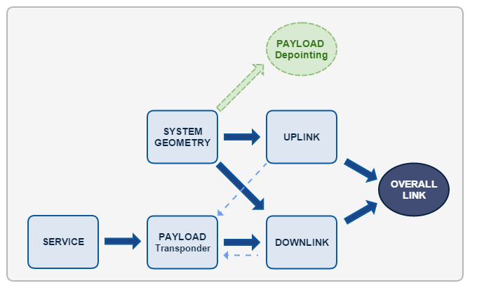
Figure 1: Order of impact of the tabs.
In Figure 1, the tables within a rectangle are those that have an impact on others. Instead, tabs within a circle are those that have no impact on others. The Payload Transponder tab is marked in a different colour because we have begun to implement the first steps for calculating the depointing angle but, as discussed in the part of Further Improvements, it is a future implementation to perform. Finally, the dashed lines going from Uplink and Downlink to Payload Transponder refer exclusively to the value of (C/No) at saturation, that is shown on the Payload tab but then it has no major impact on other tabs.
- Set all the default values button: Sets the default values for all input parameters of the current tab.
notice. The program is designed with a default value for each input parameter. Thus, the user can calculate a certain link budget without having to enter any parameters.
- Clear variables button: Resets all input values of the current tab.
$$$$
User Manual:
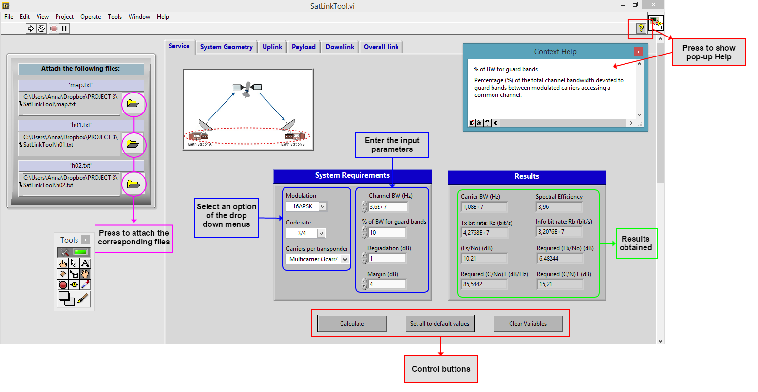
- Open the SatLinkTool.vi file with LabVIEW and click Operate/Run (or Ctrl+R) to start the simulation tool.
- Attach the files map.txt, h01.txt and h02.txt by clicking the folders on the left box.
- Fill all the parameters to match your system requirements in the empty boxes or the drop down menus of the Service tab. When you have finished, click on 'Calculate' and the results will be shown.
notice. Press the yellow question mark of the little box in the top right (or Ctrl+H) to obtain more details of each input and output parameter. Press it again to hide the pop-up box.
- Proceed in the same manner in the Geometry System tab. There you can press 'Show on the map' to see a figure with the two earth stations in a map.
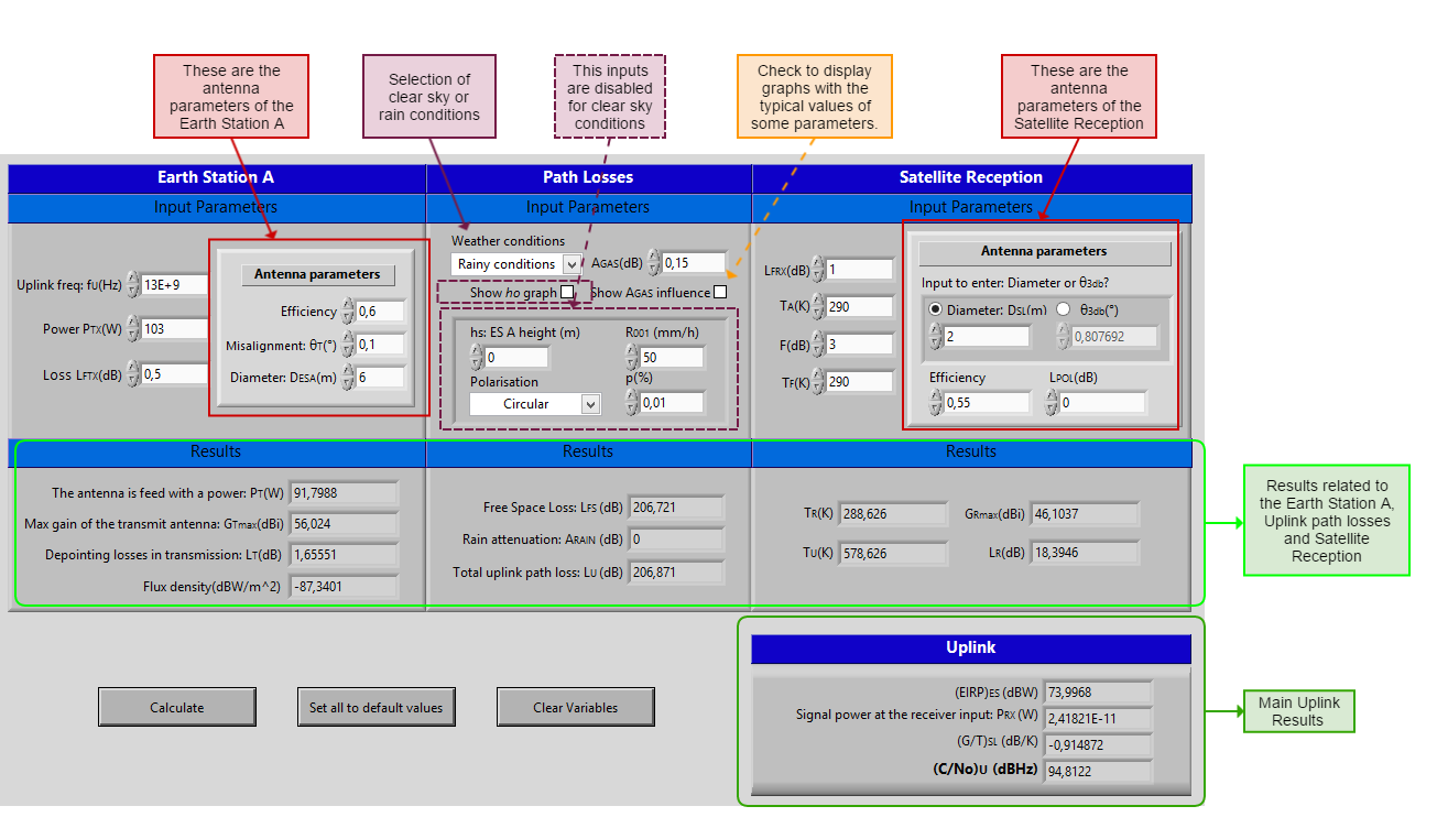
- In the Uplink tab, fill in the empty boxes all the input parameters depending if they are related to the emitting earth station, the uplink path, or the satellite reception, as shown in the figure below.
- In the Downlink tab proceed in the same manner than in the Uplink tab.
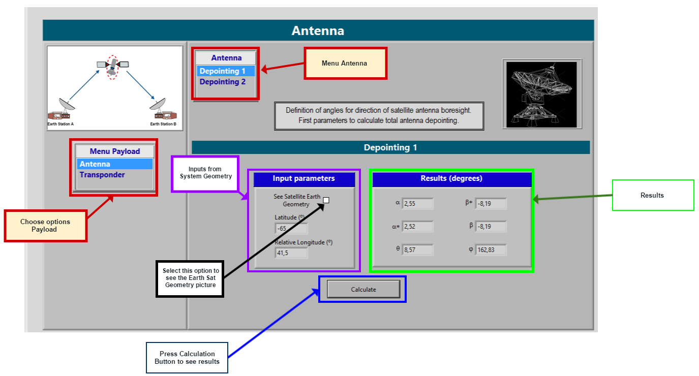
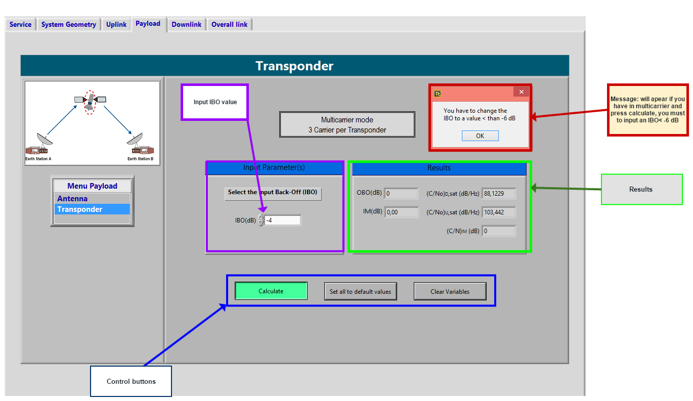
- In the Payload tab we have two options : Transponder or Antenna.
- In the Antenna tab you can perform the calculation by pressing in "Calculate button" (the input parameters can just be changed in the System Geometry tab.
- In the Transponder tab you can perform the calculation taking into account IBO and OBO parameters..
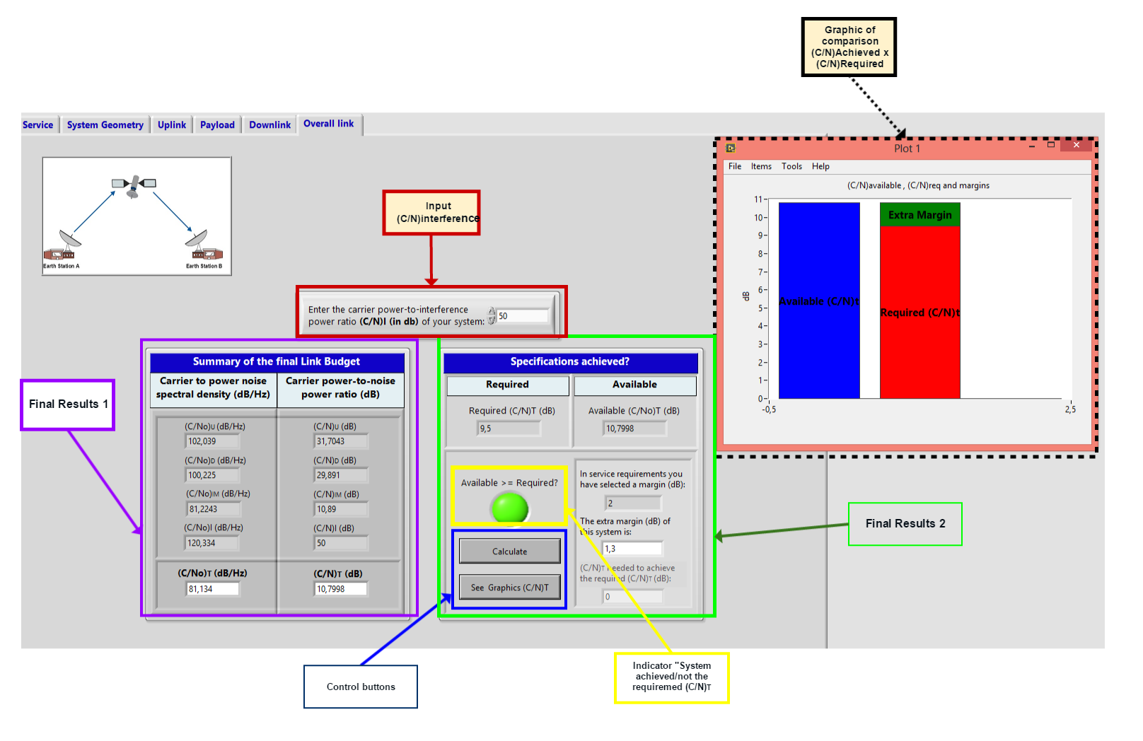
- In the Overal Results tab you can perform the final calculation taking in account all calculations done before.